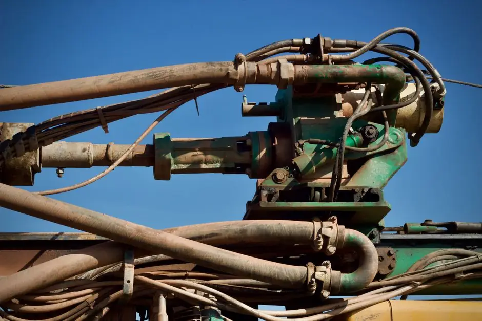
Die mounting clearance is the usable space inside the four tie bars, checked against the complete die footprint, ejector layout, tie-bar nuts, and platen interfaces.
A 68-ton DM68T zinc hot-chamber machine, for example, lists 360 x 320 mm tie-bar spacing, a 565 x 500 mm platen, 680 kN clamping force, and a 120–330 mm die-thickness range [S5].
What Tie-Bar Spacing Means for a Die
A patent titled "Means for squaring tie bars for die casting machines" describes adjustment of tie bars using an adjustment nut and detectors. It is not identical to platen size: the DM68T combines a 360 x 320 mm tie-bar opening with a larger 565 x 500 mm platen [S5].
The complete die must clear the tie bars, their nuts, and the platen-mounted components through the full clamping stroke. A valid fit therefore requires more than comparing the casting footprint with the tie-bar rectangle. Ejector rods, cooling manifolds, cover plates, guide components, and the die casting die mounting edges also occupy the available envelope [S4].
For procurement screening, the DM68T values provide a useful boundary: 360 x 320 mm tie-bar spacing, 565 x 500 mm platen dimensions, and 120–330 mm permitted die thickness [S5]. These dimensions do not by themselves establish die compatibility. The approved layout must also verify the ejector pattern, opening movement, weight support, service access, and clamping interface [S5].
Clearance Criteria That Prevent Installation Failures
Five checks should be completed before ordering a machine for an existing die: tie-bar opening, platen dimensions, die-thickness range, ejector arrangement, and clearance for handling equipment. The 2026 quick-change guidance says die weight is the first check and affects the selection of die lifters, rollers, hydraulic clamps, die carts, rail height, and loading direction.
First, draw the complete die outline, including guide bushes, locating rings, support brackets, and the moving half of the mold. Its widest and tallest points must remain inside the 360 x 320 mm opening for the DM68T reference machine [S5]. A casting that fits inside the platen can still be unable to pass between the tie bars.
Second, separate fixed-platen clearance from moving-platen clearance. Check stationary components at the rear of the moving platen, ejector travel, the shot-hole approach, and any pipes or cables attached to the tool. Third, measure the usable clamping edge on both platens, including previous modifications and damaged or deformed T-slots [S4].
Fourth, verify the shot position. A die designed around one nozzle offset may not suit a machine with a different center height; Fifth, confirm crane, roller, rail, and die-lifter access. Quick-change hardware cannot compensate for a die that cannot be loaded safely.
Compare Clearance Across Machine Configurations

Machine selection should compare tie-bar spacing, platen area, die-thickness range, and clamping force rather than clamping tonnage alone. The DM50T and DM68T list the same 0.9 kg zinc shot weight, clamp stroke, and die-thickness range, while their tie-bar and platen dimensions differ.
This comparison shows why a larger platen cannot substitute for a wider tie-bar opening. The DM68T provides more mounting area and a higher clamping force than the DM50T, but its suitability for a particular tool depends on whether the complete die fits within the 360 x 320 mm tie-bar opening and 120–330 mm thickness range.
Use Clearance Data With Clamp-Force Checks
Die fit and projected-area demand must be checked separately. The DM68T shortlist condition requires the complete die to fit inside the 360 x 320 mm tie-bar opening and 120–330 mm thickness range, while the projected-area calculation must retain an acceptable margin below 680 kN [S5].
For a quantitative starting point, die casting clamp tonnage from projected area explains why the physical envelope decision does not determine the required clamp force. Tie-bar spacing decides whether the tool can be mounted; the projected-area and cavity-pressure evaluation decides whether the machine can hold the parting surfaces under load.
The reference DM68T configuration has a 680 kN clamping force. The 215 mm stroke must be reconciled with die thickness and required shutoff or opening travel, while 680 kN must be checked against the actual projected area rather than inferred from the machine’s physical size.
Aligning the Die Protects Tie Bars and Parting Surfaces

Uneven tie-bar loading causes the die parting surface to close unevenly, producing flash and accelerating tie-bar failure.
Correct alignment is also a maintenance requirement, not merely a commissioning task. Corrosion, cracks, inclusions, improper alloying, and poor heat treatment can create a weak location, while overload or misalignment can make one tie bar exceed its capacity [S2]. A machine operated out of square or with a die that no longer applies even pressure can load the tie-bar system unevenly.
Tie-bar spacing remains the fixed geometric screening dimension, but parallel platen position determines whether that clearance translates into uniform load across all four bars.
Who Benefits from a Clearance-First Purchase
A clearance-first purchase fits tooling engineers, die makers, and procurement teams evaluating a hot chamber machine against a defined die envelope. It works best when the die drawing, thickness stack, ejector layout, shot position, and utility connections are available before model selection. [S4]
It is less suitable for an early application with an unverified die concept, because unknown sprues, slides, cores, or cooling connections can consume clearance that the tie-bar drawing does not reveal. It is also insufficient for process qualification alone, since clamp-force demand, cavity pressure, thermal growth, and platen deflection remain separate engineering checks [S3].
The DM68T reference data are suitable for initial screening because the machine provides defined values for 680 kN clamping force, 360 x 320 mm tie-bar spacing, 565 x 500 mm platen size, 215 mm clamping stroke, and 120–330 mm die thickness [S5]. Final release still depends on the approved layout and signed technical scope rather than a web specification alone.
Release the Die Fit Only After Dimensioned Verification
The next trackable engineering node is a dimensioned die-and-interface drawing showing the 360 x 320 mm tie-bar envelope, the 120–330 mm die-thickness stack, ejector components, shot position, mounting surfaces, and service clearances [S5].
After installation, verify platen squareness with a squaring block or test ring and inspect tie-bar nuts, threads, and platen surfaces for wear or damage [S2]. These checks connect the selected clearance to uniform load, controlled parting-plane closure, and reduced risk of flash or premature tie-bar failure.