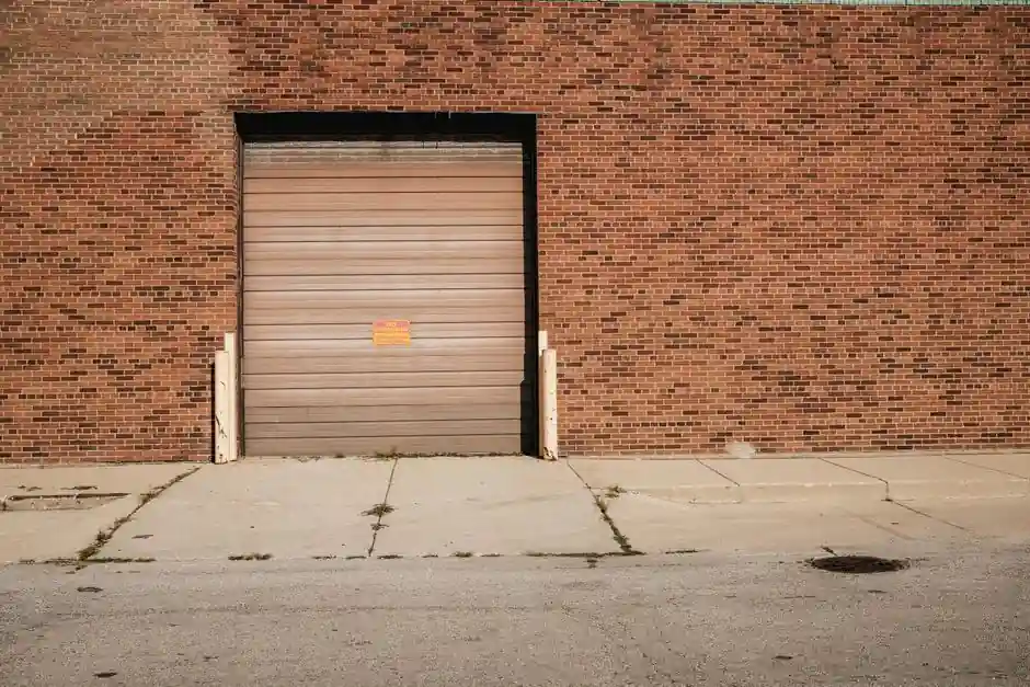
Recessed dock leveler pits fail in winter not from equipment wear but from water that pools at the pit floor, freezes, and heaves the frame anchor bolts; civil works must address both drainage and frost penetration in the same pour [S2].
Two installation paths exist: preformed pit kits (welded steel pans dropped into the slab formwork) and pour-in-pan construction (curbs cast monolithically with the slab) [S1]. Both paths converge on the same drainage and frost-protection requirements, because the pit is a precision recess, not just a hole in the floor [S2].
Pit Geometry and Concrete Grade that Set the Drainage Plane
Recessed dock levelers need a pit width set to platform width plus a manufacturer-specified clearance on each side, a pit length covering the platform plus rear clearance for the subframe and hydraulic components, and a pit depth driven by the leveler's working range and subframe height; all three come from the supplier's civil works drawing, never from a previous project [S2].
Standard recessed units serve a 12 in. above and 12 in. below dock working envelope, with special configurations reaching 18 in. above and below depending on ramp length and pit depth [S5]. Hydraulic units for general freight typically carry 6,000 kg to 10,000 kg static load ratings, and the pit floor slab must be sized for the rated point load under dynamic forklift and truck-impact conditions, not just static [S2].
Minimum concrete grade for pit walls and floor in European practice is C25/30 to EN 206, with rebar mesh sized for the rated point load and wall thickness confirmed by a structural engineer against the equipment's civil drawing [S2]. A typical Perma-style preformed kit uses 2 in. x 4 in. or 2 in. x 6 in. mid-span and front-top bracing, with 2 in. x 4 in. cleats nailed to the pit floor to anchor the pan against concrete buoyancy during the pour [S4].
Drainage Slot, Weep Hole, and Trapped Floor Drain Detail
Pit floors must slope consistently to a low point where a 25-30 mm drainage slot or threaded weep hole connects to a trapped floor drain; the slot is the cheapest insurance against the standing water that rusts pit steel, kills hydraulic cylinders, and turns into a 25 mm ice lens overnight [S2].
The pit pan itself must be level and consistent across the full surface to the supplier's tolerance, because a sloped or uneven pan twists the leveler frame, stresses welds, and shortens service life; drainage is achieved by a recess in the pan or a separate channel, not by tilting the pan [S2]. Pit seal kits then form a tight barrier around the leveler perimeter to cut energy loss, block rodent ingress, and stop water infiltration into the slot from the warehouse side [S8].
For sites with no in-floor drain, a pumped sump with a small submersible condensate pump discharging to the nearest floor drain is the field workaround, but a gravity slot to a trapped drain is preferred because pumps fail and freeze. Proper fit of the leveler inside the concrete recess, accurate leveling of the frame, and secure frame support all drive how the leveler performs under load, and all three depend on the drainage detail being correct before the pour [S6].
Frost Protection: Insulation Skirt and Footing Depth
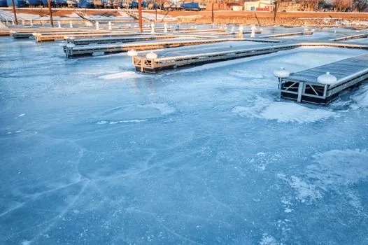
In frost-susceptible climates the pit must be treated like a shallow foundation: the underside of the pit slab and the outer pit walls need extruded polystyrene (XPS) insulation, commonly 100-150 mm thick, extending horizontally past the pit perimeter and vertically down to a depth at or below the local frost line, so the soil under the pit never freezes and heaves the frame [S2].
Frost heave is asymmetric: an insulated warehouse floor slab sits on a heated building, so the soil below stays warm, but the pit extends outside the building envelope into a zone that sees ambient winter air through the open dock door; without a continuous insulation skirt, that thermal bridge pulls the frost line down under the pit and lifts one corner of the frame relative to the others. The fix is a continuous XPS skirt, not a perimeter French drain, because the problem is heat loss, not groundwater.
For freezer or cold-storage dock positions the same logic applies at higher delta-T: the pit frame and the first 600 mm of surrounding slab need a thermal break, and the drainage slot must be heated or routed to a heated drain hub so the slot itself does not become the ice path that lifts the pan. The combination of drainage slot plus insulation skirt plus correct pit depth is what separates a pit that runs thirty winters from one that jacks the anchors out in the third.
Method Comparison: Pit Kit vs Pour-in-Pan, and Exterior No-Pit Alternative
A preformed pit kit is a welded steel pan delivered to site and dropped into the formwork; the pan acts as the drainage trough and the form face, so the slot geometry, slope, and frame anchors are factory-controlled rather than dependent on the forming crew's skill on a wet slab [S1].
A pour-in-pan build forms the pit curbs with the slab pour; it costs less in materials and shipping but shifts drainage accuracy, frame anchor placement, and frost-skirting detail onto the civil contractor, which is where most cold-climate failures originate. Three decision criteria line the methods up:
1) Dimensional accuracy: factory pan wins, because slot slope and frame anchor locations are jig-located rather than hand-formed [S1].
2) Frost-skirting integrity: pour-in-pan can match the pan kit if the XPS skirt is continuous, but field quality control is the weak link on a pour-in build [S2].
3) Retrofit cost: if the slab is already down, an exterior surface-mounted leveler avoids the pit entirely; Dockzilla's exterior unit installs on the outside of the facility in one day without permanent construction, trading working range and capacity for zero civil works [S9].
Selection Criteria by Climate, Capacity, and Duty Cycle
For cold-storage or northern-climate sites with forklift traffic above 20 cycles per day, the spec should read: preformed pit kit, C25/30 concrete to EN 206, 100-150 mm XPS skirt to local frost depth, 25-30 mm drainage slot to trapped floor drain, and hydraulic leveler with mechanical free-fall safety legs plus full-range toe guards [S2][S5].
For light-duty, mild-climate sites with fewer than 10 cycles per day and no freezer exposure, a mechanical pull-chain leveler in a pour-in pan with a simple 25 mm weep hole to a floor drain is adequate, because the frost-heave risk is low and the cost premium of a factory pan does not pay back [S5].
For sites where the slab is already cast and cannot be broken out, an exterior no-pit leveler is the third path; capacities top out well below pit-style units, but the unit can be in service the next day with no drainage or frost work at all [S9]. For new construction, the dock leveler selection drives the civil works, not the other way around.
Standards, Sourcing, and Cross-Reference
European pit construction is governed by EN 206 for concrete grade (C25/30 minimum cited) and by the leveler OEM's civil works drawing for dimensions, anchor patterns, and reinforcement sizing; ANSI MH 14.1 / MH 29.1 is the parallel US dock-equipment standard referenced in US manufacturer literature [S2][S7].
For the wider loading-bay equipment context, construction machinery and equipment selections for site grading around the dock apron, and lamps and light fittings for the dock approach, both feed off the same civil-works package. Where dock levelers share a control panel with door interlocks and vehicle restraints, the motor protection relay and protection relay sizing for the hydraulic pump motor should be confirmed against the leveler's nameplate FLA, not the breaker size, because the high inrush of cold hydraulic oil at start can nuisance-trip a marginal overload [S3].
For a related field reference on stake-out precision that feeds into pit-dimension tolerance, see outdoor rotary laser receiver range specs and selection for grading. For the concrete-side reinforcement behavior that underpins frost-skirting design, see milled steel fiber bond mechanism roughness twist and pullout behavior.