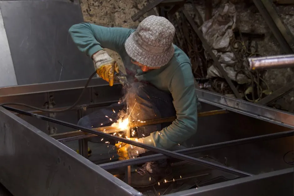
A rear frame shim pack of 1/8 in. to 1/4 in. steel, set at corners and centre and welded to both the leveler and the embedded curb angle, is the standard practice to bring the deck flush with the dock floor and absorb trailer impact loads [S1][S6].
The weld sequence is equally prescriptive: rear centre first, then rear ends, then front keepers, with stitch welds around 6 in. (152 mm) long on roughly 6 in. centres, and a 1/8 in. E7018 electrode for any field repair to the hinge tube [S5][S7][S4].
Why shim and why weld: load path and pit tolerance reality
A typical pit is 2 in. wider than the leveler to give 1 in. of side clearance for deck articulation and to absorb pit width inconsistency, which means the rear frame has to be planked up on steel to bring its top surface flush with the pit curb [S1]. Concrete, brick or timber shims compress or crush under live forklift traffic; only welded steel shims remain dimensionally stable across the 50,000–80,000 lb (22,700–36,300 kg) capacity range that covers most hydraulic and mechanical units [S1][S2]. For more on what a dock leveler is and where it sits inside the loading bay, see the equipment overview.
Unwelded shims walk out under cyclic load: a single lift-truck pass over an unsupported shim can drop the rear frame 1/8 in., opening a lip-to-pit gap that snags trailers. Weld the shim to the leveler frame first, then weld the assembly to the curb angle, so the load path runs from leveler to shim to pit steel rather than shim to leveler alone [S1][S7]. The same logic applies to the lift cylinder saddle on hydraulic units and the hold-down on mechanical units, both of which must be shimmed and welded [S1].
Shim material, thickness, and placement geometry
Shim under the rear frame at corners and at the centre, with additional shims directly under the lift cylinder (hydraulic) or the hold-down bracket (mechanical); a 1 in. side gap to the pit wall is normal and is not shimmed, since it is required for top-deck articulation [S1]. Material is mild steel, often 1/8 in. to 1/4 in. thick, stacked as needed to close the gap between the leveler base and the embedded curb angle.
For hydraulic pit levelers, the pit pan (Perma Pit or pour-in form) is set so its top angle is flush with the dock floor, with the pan pitched forward 0.5 in. toward the dock face for drainage, and the curb angle set inside a foundation opening 12 in. wider than the finished pit width; the leveler itself is anchored by the initial concrete pour and then welded down afterwards [S5]. The leveler is built slightly shorter than the pit depth, so shimming to proper height is normal rather than an indication of a miscast pit [S1].
Weld sequence: rear first, centre first, then ends, then front
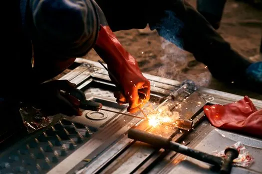
Weld the rear of the leveler to the embedded curb angle with a centre weld first, followed by welds at the ends; this provides initial restraint against thermal pull and keeps the rear frame flat while you set the front height [S5]. After the rear tack passes hold the unit square, weld the shims to the leveler frame, then weld the front of the dock leveler frame to the shims located under the keepers, then weld those shims to the front pit curb steel [S2][S3][S8].
For a vertical-style mechanical installation, weld the shims to the leveler frame, next weld the rear transition angle to the rear pit steel at floor level, then run a series of five 6 in. welds along the rear transition angle to lock the assembly [S7]. A full continuous weld is ideal; on smaller or lower-capacity units, 6 in. stitch welds spaced at approximately 6 in. (152 mm) centres are accepted by the manufacturer [S1][S8]. On a 6×8 ft, 60,000 lb hydraulic KHD-class unit, the sequence is: shim and tack corners and centre, then tack the front bottom angle, verify square and level, then run full or stitch welds across back and front angles, and grind all welds smooth [S1].
Field repair case: hinge tube fatigue and weld procedure
Hinge tube fillet welds are a documented fatigue point, especially on units that see three-wheel forklift traffic or were not originally ordered for that loading pattern; cracking typically initiates at the toe of the weld against the steel frame, with the bead on the tube still intact [S4]. Material chemistry is often unspecified mild steel, and a chemical analysis is the right first step before a repair procedure is locked in [S4].
The field procedure that has been used successfully is: grind out the failed weld where access allows, then re-weld the hinge tube with 1/8 in. (3.2 mm) E7018 electrode with preheat, using low-hydrogen practice (electrode stored at 250 °F in a holding oven, taken from sealed cans) [S4]. Heavier steel construction and heavier hinge sections on DLM and Poweramp product lines are reported to extend fatigue life compared with several competitor brands, and freezers or salt warehouses sometimes ship with special corrosion-resistant hinge materials, so verify via serial number with the OEM before specifying a repair [S4].
Acceptance criteria, common failures, and when not to repair
Acceptance after weld-down: deck flush with pit curb within 1/8 in. across the rear frame, no daylight visible between shim and either steel face, full-penetration or stitch welds per OEM (full preferred, 6 in. stitch acceptable on lower-capacity units), welds ground smooth to remove sharp edges that could cut weather seals or operator clothing [S1][S7]. Pit floor should be smooth with no bolts or concrete spalls proud of the surface, since debris under the leveler shifts the shim stack after commissioning [S1].
Common failure modes are: shims walking out because they were not welded to the leveler, rear frame dropping under live load because only tack welds were left in service, hinge tube toe cracks from underspecified weld size or three-wheel forklift overload, and lip-to-curb interference from under-shimmed front keepers [S1][S4]. Escalate to OEM replacement rather than field repair when cracking recurs within a single loading season despite correct procedure, when material chemistry is unknown and cracking has migrated into the base metal, or when the rear frame itself is bent or the curb angle is torn out of the pit steel. For context on how a dock leveler interfaces with surrounding equipment in the loading bay, the construction machinery and equipment overview covers adjacent handling assets. Adjacent fire-rated assembly tolerances for door frames in the same dock wall are detailed in this breakdown of fire door intumescent seal hardware spacing, which is the next component an installer welds and seals after the leveler is set.
Trackable signals: revised installation manuals from major OEMs (DLM DH and Poweramp PR series) continue to converge on rear-centre-first, stitch-weld-at-152 mm spacing, and 1/8 in. E7018 for field hinge repair; any deviation in the field should be verified against the serial-number-specific manual before weld current is set.
The underlying component specifications are covered under lamps and light fittings.