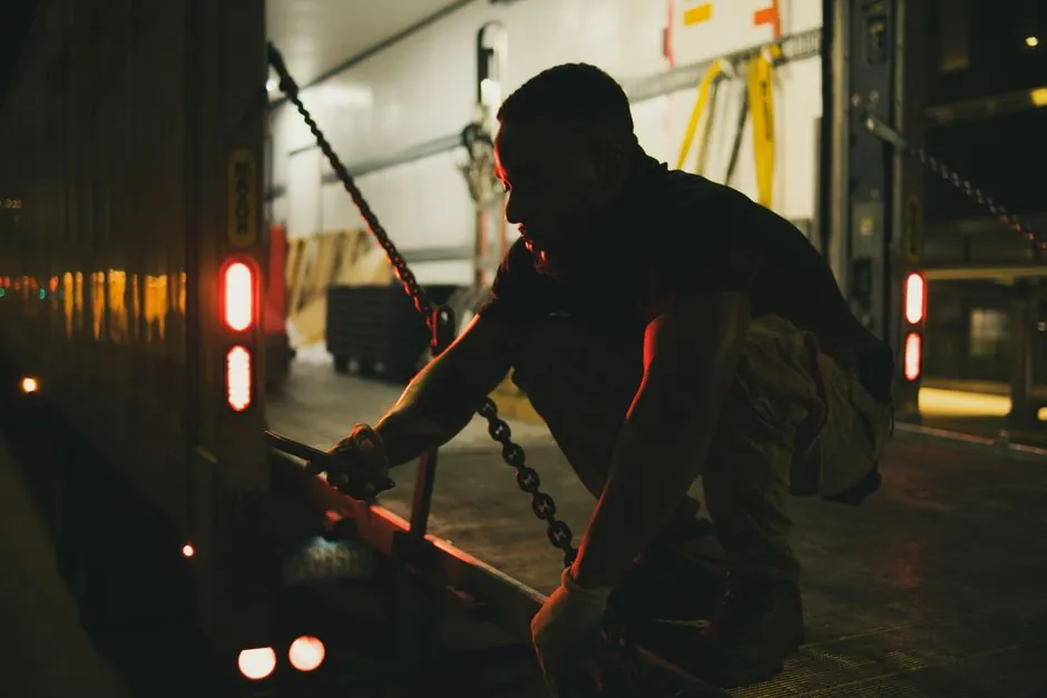
Recessed dock levelers sit in a formed pit whose depth is governed by the subframe height plus the working range, not by the lip length, and lip length is selected independently to clear the truck bed and the pit recess [S1][S2].
Standard pit length for a recessed dock leveler is a minimum of 6 ft, and the standard operating range is 12 in. above to 12 in. below dock height, with special configurations reaching 18 in. above and 18 in. below [S1][S3]. Pit width equals platform width plus manufacturer clearance, and pit depth is determined by the leveler's subframe and its working range above and below dock floor level [S2].
Why Pit Depth Is Not the Same as Lip Length
Pit depth is the vertical dimension from finished dock floor down to the underside of the subframe, set so the platform can travel its full working range without striking the pit floor, and the standard range serves 12 in. above and 12 in. below dock height [S1][S3].
Lip length is the horizontal reach of the lip that rests on the truck bed, and it must clear the pit recess (typically the void in front of the platform) and bear on the trailer bed with positive overlap, not against the pit steel [S4][S8]. The lip hinges at the front of the ramp and extends as the ramp raises, so its geometry is independent of how deep the pit is dug [S1].
Standard Numbers a Civil Contractor Must Hit
Recessed pit length is generally a minimum of 6 ft, with platform length plus rear clearance for the subframe and hydraulic components driving the final dimension, and pit dimensional tolerances on squareness, depth, width, and length are plus or minus 1/8 in. per manufacturer drawings [S1][S7].
Working range splits as 12 in. up and 12 in. down from dock height for standard units, with special configurations reaching up to 18 in. up and 18 in. down when ramp length and pit depth both support it, and pit depth is set by subframe height plus the half-range below dock [S1][S2][S3]. Hydraulic units for general freight commonly carry 6,000 kg to 10,000 kg static load, and the pit floor slab must be sized for the rated point load under dynamic forklift conditions [S2].
Decision Map: Pit Depth Sizing vs Lip Length Sizing
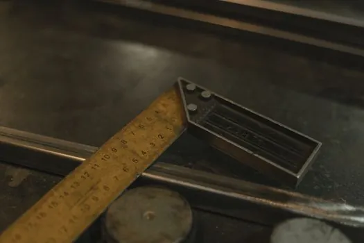
Two parameters, two different specs: pit depth is governed by subframe height plus the below-dock working range, while lip length is governed by truck bed geometry and pit recess clearance, and the two are dimensioned independently on the supplier's civil works drawing [S2][S4].
Use the table below when reviewing a supplier drawing before pouring concrete. The concrete grade callout is C25/30 to EN 206, and the tolerance callout is plus or minus 1/8 in. on all four pit dimensions [S2][S7].
Field Failures When These Two Get Confused
A pit that is too shallow causes the platform to strike the pit floor before reaching the full below-dock travel, and a pit that is too deep leaves an excessive gap that the lip cannot bridge, both of which are civil failures rather than equipment failures [S2][S4].
If the lip is too short, it lands on the pit frame steel instead of the truck bed and slips under load, and if the lip is too long, it can strike the opposite pit wall during retraction, and either case forces rework of either the lip selection or the pit recess depth [S4][S8]. Rechecking pit width, depth, length, and lip recess against the leveler specification before equipment arrives eliminates the most common causes of delay and damage [S2][S8]. For a closer look at how deck plate steel grade interacts with these structural dimensions, see the dock leveler deck plate thickness vs yield strength spec map.
Concrete and Reinforcement Around the Pit
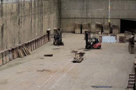
Pit walls and floor must be reinforced concrete, with a minimum grade of C25/30 to EN 206 or the equivalent national standard, and rebar mesh sized for the rated point load under dynamic forklift and truck approach conditions [S2].
Minimum wall thickness must carry the frame anchor loads and must be confirmed by a structural engineer against the equipment's civil works drawing, and the pit frame, a steel angle or channel section bordering the opening, is anchored into this concrete [S2]. Sloped or uneven pit floors twist the leveler frame, stress the weld joints, and shorten service life, so the floor must be level and consistent across its entire surface per the supplier tolerance [S2].
Mechanical vs Powered Levelers, and Why It Changes Pit Depth
Mechanical spring-loaded levelers are held down by a releasable hold-down device and lifted by walking the ramp out, with mechanical safety legs that stop free fall more than 4 in. below dock level, and this simpler subframe allows a shallower pit in some configurations [S1][S3].
Hydraulic and air-powered levelers need rear clearance for the hydraulic cylinder or air bag, and the powered subframe is taller, so the pit depth callout on the civil drawing for a powered unit is typically greater than for a mechanical unit of the same working range, which is why substituting dimensions from a different model is a common and costly mistake [S2][S3]. Powered units also support constant-pressure push-button activation and interlocking with motorized overhead doors, adding to the rear-component envelope that drives pit length, not pit depth [S1][S3].
Sourcing, Standards, and What to Confirm Before Pour

All three pit dimensions (width, length, depth) must come from the supplier's civil works drawing for the specific model ordered, with tolerance plus or minus 1/8 in. on squareness, depth, width, and length, and the lip length must be cross-checked against the same drawing so the lip clears the pit recess [S2][S7].
Confirm the concrete grade callout (C25/30 to EN 206 or equivalent), the rebar sizing for the rated dynamic point load, the working range (12 in. or 18 in. up and down), and the powered-versus-mechanical subframe height before any concrete is poured, because none of these are interchangeable between models [S1][S2][S3]. A short-lip versus long-lip decision is driven by the trailer bed geometry at the loading bay, not by the pit depth, and the working range split of 12 in. up and 12 in. down is the most common spec for general freight in 2026 [S1][S2][S3].
For component-level specifications, see dock leveler, pressure transmitter, and flow meter.