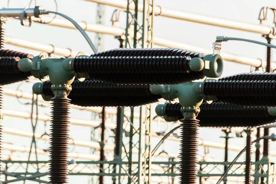
A dry-type transformer is sized in kVA from the connected and demand load on the panel it feeds, with the unit picked at the next standard rating above that figure plus 20–30% headroom [S6][S5]. Standard kVA taps commonly run 30, 50, 80, 100, 125, 160, 200, 250, 315, 400, 500, 630, 800, 1000, 1250, 1600, 2000, 2500, 3150, 4000, 5000, 6300, 8000, 10000, 12500, 16000, 20000, 25000, 40000, available in copper or aluminum windings with cast-resin, VPI, or amorphous cores [S1].
These units are built to NEMA, ANSI C57, DoE, and IEEE family standards, with 50/60 Hz ratings, 80°C/100°C/125°C rise options, and C2/E2/F1 environmental classes covering most indoor industrial, commercial, hospital, and data-center duties [S1]. The core reference page on dry-type transformer covers the construction options (cast resin vs VPI vs amorphous) and the cooling classes (AN/AF) that drive the next round of decisions.
Start from the load, not the catalog
Capacity (kVA) is the single most important selection parameter, and field practice is to size at roughly 120–130% of calculated peak demand to absorb future expansion without running the unit at continuous over-temperature [S5]. For a three-phase load the basic relation is kVA = kW / power factor; a 120 kW load at 0.9 PF requires about 134 kVA, so the next standard 160 kVA frame is the realistic pick [S4]. Most dry-type efficiency sweet-spots sit in the 70–80% loading band, which is why a slightly oversized transformer is preferred over a tightly matched one for variable commercial and hospital loads [S5].
The sizing flow in the field runs panel load → demand factor → next standard kVA with margin → impedance check → physical fit → ventilation → tap range. A typical three-phase 10kV/0.4kV indoor unit dominates new European and Asian commercial builds because it slots directly between the MV utility feed and a 400 V four-wire distribution, the configuration most facility switchgear is wired for [S7]. Related cross-discipline selection logic, including how sensor range and accuracy factor into the same kind of margin decision, is detailed in temperature sensor sizing and selection.
Voltage classes, taps, and impedance
Common MV primary levels for indoor dry-types are 6, 10, 11, 20, 22, 33, and 35 kV, with the 10 kV/0.4 kV combination the most widely specified for industrial and commercial distribution [S5]. Primary-side taps at ±2×2.5% are the typical default to compensate for utility feed voltage drift, and the unit must be specified either Δ or Y to match the upstream network [S5][S1]. Secondary outputs land at 400 V, 415 V, 480 V, 690 V, or 3.3 kV depending on the downstream bus, with 400 V three-phase four-wire dominating commercial buildings and 480 V common in North-American data halls [S5].
Impedance (Uk%) typically lands between 4% and 6% on standard dry-types, and that number controls short-circuit current, downstream breaker coordination, and whether two transformers can be paralleled [S5]. A 1060 kVA 480 Δ to 415Y/240 V unit in a representative containerised data-center build is a concrete example of a 60 Hz, cast-resin, step-down configuration used for that duty [S1].
Cooling method and physical envelope
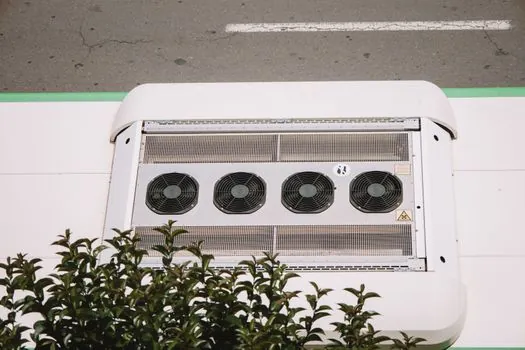
Dry-types use either natural air cooling (AN) or forced air cooling (AF), with AF versions adding fans that slightly inflate width and depth but recover roughly 30–40% of additional kVA capacity on the same frame [S4]. Core-and-coil envelope scales sharply with rating: a 5 kVA resin-cast unit is roughly 600×400×700 mm at 50–100 kg, while a 2500 kVA unit lands near 3200×1800×3200 mm, and a 1000 kVA SCB11 frame typically weighs around 2800 kg [S3][S4].
Standard SCB10, SCB11, and SCB12 series share a dimensional family: 100 kVA ≈ 900×750×1100 mm at 600 kg, 630 kVA ≈ 1450×1050×1350 mm at 1800 kg, and 1600 kVA ≈ 1850×1450×1600 mm at 4100 kg, which lets engineers plan switchroom layouts against a single dimension table before manufacturer drawings arrive [S4]. Above 2000 kVA, smart top-and-bottom air ducts become common, and the room layout must preserve clear airflow paths in addition to front/side access clearances [S4].
Installation clearances and ventilation
Field practice sets a minimum of 1.2 m front clearance, 0.8 m side clearance, and 0.8 m top clearance for any dry-type, with explicit airflow gaps on sides or base to prevent hot-air recirculation [S4]. In dusty or outdoor-tunnel environments, mesh guards or enclosure covers are added to keep particulate off the windings, even though the resin or VPI encapsulation already provides an F1 fire-safety class [S4][S5].
Heat extraction in indoor electrical rooms is sized off the no-load and load-loss numbers, and on most modern cast-resin designs total losses are low enough that the room does not need forced extraction below 1000 kVA if walls are at least 3 m from the unit [S9]. For above 2000 kVA, paired supply/extract fans and a top vent are the typical engineered solution, with the duct path designed so that hot air cannot short-circuit back to the intake [S4]. Where heat-detector selection intersects this envelope, point, rate-of-rise, and linear options are mapped in heat detector selection for mining operations, a useful parallel for transformer-room fire design.
Losses, efficiency, and where to push back on oversizing

No-load losses are dominated by core material, with amorphous cores delivering the lowest idle watts at the cost of larger frame dimensions and higher unit price; load losses scale with winding resistance and operating temperature, and are the larger number once the unit spends most of its life above 50% load [S5][S1]. DoE efficiency tiers in North America and the EU Tier 2 regulation both push designers toward lower-loss cores for continuously operated units, while lighter-duty standby transformers still often use grain-oriented silicon steel on a cost basis [S1].
The most common field error is over-sizing beyond about 130% of peak demand, which raises first cost and drives no-load losses upward for the life of the unit, because the transformer sits at a low loading percentage 24/7 even when the facility is at full output [S7]. The opposite error, picking a unit at 100% of calculated demand, leaves no margin for load growth and is the more frequent cause of insulation thermal ageing and unexpected fan tripping after 12–24 months in service [S7].
Who dry-types are for, and where they should NOT be specified
Cast-resin and VPI dry-types are the default pick for hospitals, shopping centers, airports, metro stations, data centers, high-rise buildings, and indoor substations where fire-safety F1 rating, low maintenance, and zero oil-leak contamination risk outweigh the higher first cost versus oil-immersed units [S5][S2]. They are also the natural choice for compact substations on construction sites and for containerised modular data halls where the transformer lives inside the same enclosure as the IT load [S1][S2].
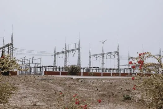
Dry-types are the wrong pick for outdoor substation bays above 35 kV, very large utility step-downs above about 20–25 MVA where oil-immersed still wins on footprint and cost, and any site where ambient ventilation cannot keep the windings below rated temperature rise. Specifying a dry-type for a remote outdoor switchyard without enclosure heating invites condensation failures; an oil-immersed unit with the appropriate breather and oil preservation system handles that duty more reliably [S5].
Decision snapshot: cast resin vs VPI vs amorphous
For indoor data halls and hospitals, cast-resin is the default: low fire load, low maintenance, robust against humidity, but heavier and slightly larger than VPI at the same kVA [S2][S3]. For industrial plants with higher mechanical stress and thermal cycling, VPI (Vacuum Pressure Impregnated) dry-types are more tolerant of overload and short-circuit forces, with a lower first cost than cast resin at the cost of higher maintenance on the insulation system over 20+ year service lives [S1]. For continuously loaded 24/7 sites where energy cost dominates, amorphous-core dry-types cut no-load losses by 60–70% versus grain-oriented silicon steel, justifying the higher purchase price and larger frame on a 5–10 year payback basis [S1][S3].
Procurement signals and lead times
Standard kVA ratings from 30 to 2500 are widely stocked, with typical containerised data-center 1060 kVA frames quoting around 9 weeks in 2025 build slots [S1]. For hyperscale data halls the unit count is the real swing factor: a 5000 kVA+ installation typically uses multiple 2.5–5 MVA dry-types in an N+1 or 2N string rather than a single oversized unit, to keep each transformer in its 60–80% efficiency sweet spot and to allow concurrent maintenance [S2]. Sizing logic on related heavy-electrical gear, including a current 2026 spec map for industrial trucks used in the same plants, is covered in mining dump truck selection.
Track three signals over the next two quarters: Tier 2 efficiency compliance enforcement dates for non-DOE export markets, the spread of ±2×2.5% vs ±5% tap ranges on new 10kV/0.4kV builds, and whether amorphous-core pricing closes the gap with grain-oriented silicon steel for sub-1000 kVA frames. Any of those would change the shortlist logic above for a 2026 spec.
Spec-level background on the components involved: linear guide, and crossed roller guide.