
A 2–6-stage telescopic hoist spans 20–120 metric tons of lift capacity, 1,500–6,500 mm of stroke and 180–250 bar operating pressure, so bed length must be translated into mount geometry before selecting stages [S1].
Bed length affects tipping angle, stroke requirement, frame loading and mounting arrangement, but it does not determine stage count by itself; payload mass, cylinder base position, body attachment point and pivot location remain controlling inputs [S4].
What stage count actually controls
Each extending stage has a smaller effective piston area, so available push falls as the hoist advances. S1 lists dump-truck hoist capacities, stage ranges, maximum stage outside diameters, total strokes, and operating pressures, but does not provide the stated bore progression or force values.
That force taper is intentional: the largest outer stage supplies breakaway force, while smaller stages provide travel after the load has broken free [S1][S4]. More stages permit a long stroke within a short retracted length, but they add seals, wipers and internal stop components that must operate together without binding or losing load control [S1][S2].
Published selection bands associate 3–5 ton applications with 2–3 stages, 10–20 ton with 3–4 stages, 25–40 ton with 4–5 stages, and 50–120 ton with 5–6 stages [S1]. These are useful starting envelopes, not a bed-length rule. A heavy load over a long body can demand greater stroke even when stage count appears modest, while a shorter body can require a different mounting geometry rather than another stage [S4].
Convert bed length into stroke and tipping angle
S4 states that the distance between the body hinge and cylinder mounting point affects required lifting force, but the supplied excerpt does not establish numerical tipping-angle ranges for discharge. The bed length, rear hinge and cylinder attachment geometry determine whether the available extension reaches that angle.
A long body does not automatically require more stages if the cylinder can produce enough stroke and the mounting geometry creates an acceptable lift triangle. Conversely, a short body can still require a long-stroke hoist where frame clearance, vertical lift or a high tipping angle is needed [S4]. A conventional telescopic cylinder also retracts to a much shorter length than a single-stage cylinder delivering comparable stroke, which is why it is the usual dump-body solution where chassis space is constrained [S1][S7].
Mount placement can change structural results even when two arrangements produce the same final bed angle. S5 documents a proposed 4 ft × 8 ft dump-bed trailer using cylinders that are 38 in long when closed and 68 in long when extended, with both arrangements said to raise the bed to about the same angle. S5 records one respondent's view that neither cylinder placement was very good and identifies the respondent's own trailer arrangement as closest to the right-hand drawing.
Compare the principal hoist options

Telescopic and scissor hoists both raise dump bodies, but they distribute packaging, geometry and maintenance requirements differently. A telescopic cylinder uses 2–6 nested stages for long strokes from a compact retracted package [S1], while a scissor hoist uses a hinged lifting frame whose installed height and geometry determine tip angle [S8].
On stroke packaging, telescopic wins where chassis space is restricted because the stages nest axially [S1][S7]. On adjustment and service access, a scissor system offers a different architecture because its pivot geometry and base height are selected as a coordinated assembly rather than through nested bores [S8]. On force retention, neither type should be selected by stage count alone: the telescopic hoist must be checked through every extension, while the scissor hoist must be checked across its lever arms and full range of motion [S4][S8].
For a rigid dump truck or end-dump trailer with a long body and restricted frame space, a multi-stage telescopic cylinder is the default candidate. For a shorter-wheelbase chassis requiring more vertical body lift, an underbody-mounted telescopic cylinder may provide better geometry, while a scissor hoist is worth comparing when its adjustable base height and discharge angle suit the installation [S1][S8].
Payload, pressure and flow set the working envelope
System pressure supplies the force, while pump flow governs lift speed and cycle time. A 200 mm bore at 200 bar develops approximately 628 kN, but that is not the total permissible load because the cylinder mounting angle, bed weight, payload, friction and tipping geometry reduce the useful vertical component [S1][S4].
Higher pressure can reduce required bore while increasing seal and barrel stress, so operating at the maximum available tractor or truck pressure is not a substitute for matching the cylinder [S1]. In a discussion of a 14 ft dump body using a large three-stage single ram, one respondent advised avoiding bottoming the cylinder or installing a pressure-relief valve to limit maximum pressure at the end of the stroke.
Flow rate determines how quickly each stage advances, while reservoir capacity determines whether the system can supply the cylinder volume without aeration or pressure loss.
Front-end and underbody mounting
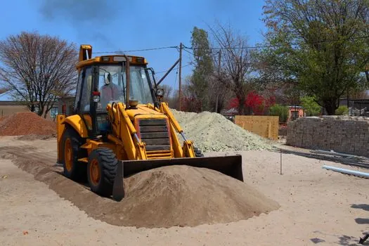
Front-end telescopic hoists mount beneath the front of the dump body and push upward from the pivot region, supporting a high lift angle and stable discharge. Underbody hoists mount below the chassis center and lift the body more vertically, making them a common fit for shorter wheelbases and tippers [S1].
Moving the cylinder base closer to the rear hinge reduces required stroke but sharply increases initial force because the mechanical advantage becomes worse. Moving it too far rearward can leave the cylinder without an effective upward vector and direct thrust into the hinge and chassis, creating dead-angle conditions [S4]. Underbody placement therefore cannot be selected from bed length alone; chassis length, rear overhang, pivot location and discharge angle must be checked together [S4][S8].
Front-end and underbody systems also differ in body and frame loading. The front-end arrangement suits heavy, long-chassis vehicles such as 8×4 trucks, whereas underbody mounting is preferred where a shorter wheelbase needs enhanced stability [S4]. The dump truck architecture therefore determines the cylinder packaging envelope before the manufacturer chooses bore, stage ratio and mounting eye details.
Failure modes and installation constraints
Cylinder top-out is a specific failure condition: once the piston reaches the end of its travel, hydraulic pressure can act directly against end structures and seals rather than producing useful lift [S3]. Avoid full top-out with a controlled relief arrangement or mechanical stop, and confirm that the selected extension does not impose unintended loads at maximum stroke [S3][S4].
Misalignment also converts lift force into frame bending, hinge-pin bending and bracket fatigue. An initial push too nearly horizontal can load the rear hinge instead of lifting the body, while excessive cylinder forces can accelerate frame cracking [S4]. The base mount, body attachment and hinge should be checked as one geometry, including side-load tolerance and the external wiper arrangement used to exclude road grit and moisture [S1].
Typical construction uses honed ST52, E355 or 1026 DOM steel tubing, hard-chrome-plated rods, polyurethane or fabric-reinforced seals, internal stop rings and external wipers. The mounting arrangement is commonly a trunnion or spherical bearing at one end and a pin-eye or foot bracket at the other [S1]. Those construction details matter during replacement because equal stroke alone does not guarantee equal mounting geometry, stage ratio, side-load capacity or sealing performance.
Specify from a complete data sheet
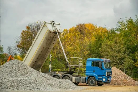
Before ordering, record payload, bed length and width, hinge coordinates, cylinder base location, body attachment location, required tipping angle, maximum pressure, available flow, reservoir capacity, closed length and required extension. Do not release a stage count until the closed and extended positions have been checked geometrically for the intended body [S1][S4].
For replacements, identify the OEM model, stage count, closed length, fully extended length, mounting dimensions, bore progression, pressure rating and rod diameter. The available interchange example lists OEM model, stage count and closed/extended length as minimum dimensional references, while the broader selection data requires truck capacity and mount geometry [S1].
A hydraulic cylinder with more stages is not automatically the better match for a longer bed. Require a drawing that shows every stage extension, the mounting triangle, maximum force and target tipping angle; then confirm that the hydraulic pump can deliver both required pressure and flow without overheating or starving the reservoir.