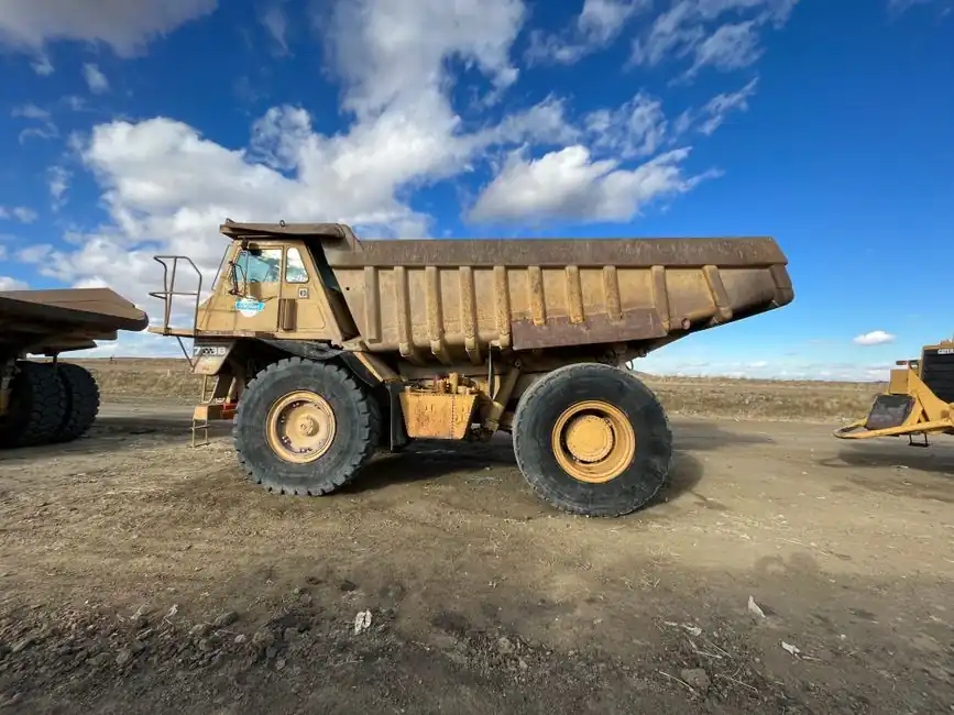
A 2.3 cubic-inch pump running at 1,000 RPM delivers about 10 GPM, so a staged hoist can use its calculated cylinder volume to set the required lift flow [S4].
Pump selection must reconcile bore, stroke, target raise time, PTO ratio, engine operating speed, system pressure, and reservoir capacity rather than rely on pump size alone [S1][S2].
Calculate Hoist Flow From Cylinder Volume
For a single-acting telescopic hoist, calculate each stage’s piston area from its bore, multiply by the stroke, add the stage volumes, and divide by 231 to obtain gallons [S4].
The governing calculation is “Flow (GPM) = Cylinder Volume (Gallons) / Target Cycle Time (Minutes)” [S1]. Pump flow should be matched to the hoist cylinder’s total volume and desired extension and retraction cycle times [S1].
The result is a duty-cycle flow requirement, not the maximum flow the circuit can tolerate. For example, a cylinder requiring 4 gallons in 30 seconds needs 8 GPM during lift; allowing for actual operating speed variation and losses, the installed pump should be matched against the complete circuit rather than accepted on nominal nameplate flow alone [S1][S4].
A cylinder bore and stroke are indispensable. A documented dump-hoist example used a 7-inch bore, although its stroke and total volume were not supplied [S3]. Older interchange data should therefore be treated as a lead, not as a sizing specification [S3] (2007-08).
Convert Pump Displacement and PTO Speed
For a gear pump, “Flow in GPM equals displacement in cubic inches multiplied by pump RPM divided by 231” [S4]. Pump speed is calculated from engine RPM multiplied by the PTO ratio [S4].
The useful working-point method is “displacement = GPM × 231 ÷ RPM” [S7].
The main comparison is between required flow and available flow at the selected engine operating point.
These ranges help screen candidates, but the final selection must use the truck’s actual gearbox ratio and the engine speed operators use while hoisting [S1][S2].
Compare Dump Pumps, Gear Pumps, and Piston Pumps

A single-function dump hoist is best served by a dump pump because the pump, relief valve, and directional control can be combined in one housing and operated by a cab cable or air shifter [S4].
A separate gear pump with an individual valve bank offers greater circuit flexibility and higher continuous-pressure capability for multi-function equipment such as a hook lift or roll-off [S4].
On flow accuracy, the dump-pump arrangement has the simplest controls but still depends on correct displacement and speed; the separate gear-pump arrangement allows more circuit functions; the piston-pump option provides the greatest flow modulation but adds cost and complexity [S4].
Pressure and flow are separate constraints. The load sets operating pressure, while the pump must withstand that pressure and the PTO must transmit the required torque [S4]. Pump type alone does not establish system suitability.
Check PTO Torque Before Selecting Displacement
Pump-shaft torque in pound-feet is approximately “displacement in cubic inches multiplied by pressure in PSI divided by 75” [S4]. A 2.3 cubic-inch pump at 2,500 PSI therefore requires about 77 lb-ft, while a 4.5 cubic-inch pump at the same pressure requires about twice that torque [S4].
Compare calculated torque with both the PTO’s intermittent rating and the transmission manufacturer’s PTO limit [S4]. This check prevents a large piston pump from overloading a light-duty PTO, a documented failure mode in wet-kit pump selection [S4].
The cited dump-pump guidance gives a typical system-pressure range of 16–25 MPa, equivalent to approximately 2,320–3,626 PSI [S2]. At either end of that range, a high-displacement pump can impose substantially more shaft torque than a smaller unit, so pressure and displacement must be evaluated together [S2][S4].
Match the Cylinder and the Dump Truck Installation
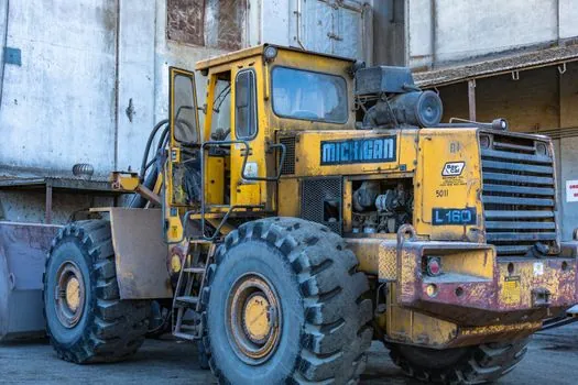
The hydraulic dump truck circuit includes the PTO, pump, directional and check valves, pressure relief, filter, reservoir, hoses, and telescopic cylinder [S2]. A correctly sized hydraulic cylinder determines the oil volume and lifting force; the hydraulic pump determines whether that volume can be moved at the requested speed.
Suction plumbing needs more attention than the discharge line. The suction hose should be one size larger than the pressure hose to reduce inlet restriction, because cavitation caused by an undersized suction line is identified as a leading cause of early gear-pump failure [S4].
For a PTO-driven installation, shaft speed, shaft load, mounting hardware, and bearing arrangement all matter. A bushed pump shaft designed for direct PTO coupling may not tolerate belt or chain side loading [S5].
Control Overspeed Flow and Hydraulic Heat
An oversized pump can exceed the flow capacity of the hoses and directional valves, increasing friction and heat [S1]. Higher flow can also create inlet vacuum, promote cavitation, and contribute to premature seal and valve damage [S1].
The suction-side limit is practical: if the pump cannot keep the inlet full, increasing engine speed does not produce clean additional flow. The comparison is therefore between commanded flow, measured pump flow, and the inlet conditions required to sustain that flow [S4].
Continuous-operation systems need deliberate cooling planning, especially when relief-valve bypass converts pump power into heat. A hydraulic oil cooler becomes more important as operating time and bypass energy increase [S4]. For short hoist cycles, reservoir cooling and the intermittent duty cycle may dominate, but that should be verified against the actual work pattern [S4][S5].
The speed target should be established from the body manufacturer’s quoted bore, stroke, and expected raise time, then checked against measured engine and PTO speed [S4]. For older military dump-truck data, an optical or photo tachometer can establish the actual PTO-to-engine speed relationship where gearing documentation is unavailable [S3] (2007-08).
Specify and Verify the Complete Hydraulic Set
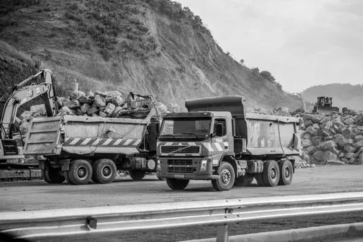
The purchase specification should list required GPM, maximum and continuous pressure, pump displacement, rated input RPM, required shaft torque, PTO ratio, shaft configuration, reservoir capacity, and minimum suction-line size [S1][S4].
For the worked wet-kit example, the calculation starts with a 2.3 cubic-inch pump at 900 engine RPM and a 1.0 PTO ratio, producing about 9 GPM, followed by a torque comparison at the selected operating pressure [S4]. The same procedure applies to a higher-displacement candidate by recalculating both flow and shaft load.
Acceptance testing should confirm actual flow at the normal hoist engine speed, pressure without a relief bypass, stable PTO engagement, acceptable oil temperature, and full extension of every telescopic stage [S1][S2]. The pump should not be accepted solely because its catalogue maximum flow is higher than the calculated requirement.
The decisive engineering check is a three-way match: cylinder volume divided by target lift time, pump displacement multiplied by actual PTO speed, and torque demand checked against the PTO rating. If one of the three fails, the mining dump truck hoist will either lift too slowly, circulate excess flow, or overload its drive equipment [S1][S4].