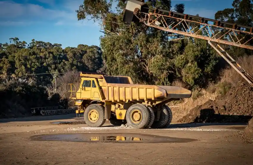
A wheel loader should approach a dump truck at approximately 45 degrees with about 5 degrees of articulation, while working from the pile toward a truck positioned to receive the load [S1].
The method links loader geometry, truck placement, bucket capacity, and boom-control functions, making it suitable for repeated loading of highway haul trucks where cycle time, payload consistency, and equipment clearance determine productivity [S2][S3].
45-Degree Geometry for Controlled Truck Loading
The loader’s initial approach is about 45 degrees relative to both the material pile and the dump truck. It then moves forward while curving right toward the pile, fills the bucket, reverses to the 45-degree starting position, and advances toward the truck [S3].
The truck should remain stationary during loading because repositioning it during each pass expands the loader’s travel distance and introduces unnecessary truck and loader movements [S3].
This geometry is not a universal clearance measurement. It is a working-position reference for a wheel loader and dump truck operating as a coupled loading system. The usable angle still depends on the loader turning radius, bucket reach, pile shape, truck-bed position, and site obstructions.
Y and V Cycle Selection
The Y or V pattern begins with the truck’s rear just beyond the pile edge and the loader at about 45 degrees relative to the pile and truck. The loader completes a right-hand curve into the pile and a left-hand curve into the bed during each cycle [S3].
The 45-degree position gives the loader two distinct work phases: a digging pass directed toward the pile and a discharge pass directed toward the truck. Maintaining the same reference angle lets the operator repeat a controlled sequence instead of searching for a new approach on every pass [S3].
The pattern is most useful where the loader must reverse toward the pile and discharge while moving forward toward the truck. It is less suitable where reversing presents a blind-side hazard, a steep side slope makes the loader unstable, or the available workspace cannot accommodate the full loader length and turning sweep.
Truck Positioning Controls the Loading Envelope
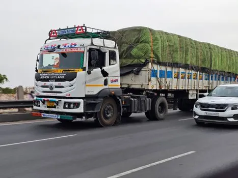
The pocket arrangement lets successive passes progress from left to right without repeatedly driving around a randomly parked truck.
Consistency is a measurable operating requirement: the Y cycle should not become so large that the loader travels unnecessary distance or so small that the loader lacks room to maneuver [S3]. A stable truck position also makes it easier to repeat the same fill point, discharge height, and bucket pass.
For specification planning, the dump truck should be considered as part of the loading system rather than as a passive container. Bed length, rear overhang, wheel path, approach visibility, and the loader’s swept path must fit within the available loading pad.
Bucket Capacity and Pass Counting
Bucket selection starts with dump-truck capacity and the number of loads required per day, then moves to the loader manufacturer’s stated maximum capacities and tipping-load limits [S3]. The selected bucket must fill the truck in as few passes as possible without exceeding those machine limits [S3].
Three quantities define the comparison: truck payload per pass, material volume moved per bucket, and the number of truck loads planned for the shift. A theoretical bucket-count calculation is only valid after accounting for fill factor and the difference between heaped capacity and struck capacity, so those operating inputs must be established for the material being handled.
A larger bucket is not automatically the better choice. If it exceeds the loader’s working envelope, slows the dump cycle, creates a spill risk, or increases the load on the truck, the nominal capacity advantage is lost [S3]. Match the bucket to the loader, truck, material density, and required daily tonnage rather than to bucket volume alone.
Boom Controls Reduce Repeatability Errors

These functions reduce operator corrections and repeat the same machine geometry more consistently.
The functions do not replace the 45-degree approach, but they support repeatable execution of it.
For a fleet evaluating mining dump truck or off-highway haul equipment used at a transfer or loading point, verify machine manuals for boom height, bucket geometry, payload distribution, and approved loading behavior. The cited guidance identifies these functions as loader features, not universal requirements for every truck body [S1][S3].
Field Limits, Safety and Cycle Verification
A usable loading cycle combines a 45-degree reference position, about 5 degrees of loader articulation, a stationary truck, and enough space for the complete Y or V path [S1][S3]. A trial pass should verify that the bucket clears the truck body, pile edge, and other equipment while retaining a consistent dump point.
The procedure does not provide a fixed permissible pile height, truck-bed clearance, or loader approach speed. Those values must come from the equipment manuals, site risk assessment, and material-handling plan. Operators also need a clear view of the reversing truck, exclusion area, and reversing alarm or camera arrangements required by the site.
The most useful field measurements are cycle time, passes per truck, truck payload, spillage, loader travel distance, and operator corrections per shift. If the loader travels farther than necessary, the pocket is oversized; if the operator repeatedly adjusts the bucket or boom, the selected control features or machine setup are not reproducing the intended cycle [S3].
Track five numbers before standardizing the 45-degree method: seconds per loader pass, bucket passes per truck, payload by scale, spillage per load, and loader travel distance per cycle. Stable values across at least three consecutive trucks will show whether the 45-degree position, about 5-degree articulation, truck pocket, bucket size, and boom-control settings work together as an engineered cycle [S1][S3].