An optical-scattering or laser-based dust detector is a fixed air-quality or stack-emission instrument that samples an airstream, counts or masses particulates in a defined size window, and outputs a 4-20 mA analog, RS-485 Modbus, or relay signal to a PLC, BMS, or emission-monitoring data acquisition system (DAHS) [S1].
Correct siting of the sample probe plus correct cable routing is what separates a passing installation from one that drifts within weeks. The most common field complaint — a stable reading indoors, a wildly swinging reading outdoors — almost always traces to the inlet placement, not the sensor itself.
Step 1 — Match the sensing principle to the particulate target
Light-scattering photometers, laser-diode counters, and beta-attenuation mass monitors each cover a different window of the particle size distribution. Most fixed industrial dust detectors specified for HVAC, cleanroom, or stack service use a laser diode at 650 nm or 780 nm and report in mg/m³ or µg/m³ after a conversion factor tied to refractive index [S1].
For PM1.0/PM2.5/PM10 service the instrument must resolve size bins; for total-dust (TSP) service a single integrated mass reading is usually enough. Specify the principle, the size window, and the output range in the same line of the P&ID so commissioning has a fixed target.
Step 2 — Site the sample point per duct geometry and ISO 21501-4
Sample-point location is the single highest-leverage decision in a dust-detector installation. ISO 21501-4 and most emission-monitoring codes require the measurement traverse to sit at least 6 duct diameters downstream and 3 duct diameters upstream of any bend, damper, or stack exit; readings taken closer to a disturbance can swing by 30-80% versus a fully developed flow profile. [S1]
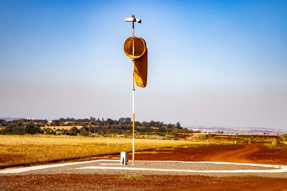
For ambient-air (open-atmosphere) service, mount the head 1.5-3 m above grade, away from building walls by at least 5 m, and away from localized sources (exhaust fans, loading bays) by at least 10 m. Vertical orientation of the inlet, with the rain shield fitted, is mandatory for outdoor units — a horizontal inlet pulls in wind-driven false counts.
Step 3 — Run power, signal, and comms cable to the right spec
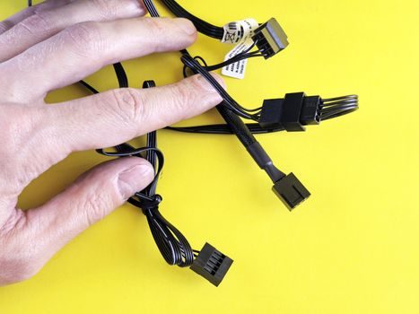
Power is normally 24 VDC at 0.5-1.5 A or 100-240 VAC, with a dedicated breaker on the instrument loop. Signal cable for 4-20 mA loops is 2-conductor shielded, 18-22 AWG, with shield grounded at the panel end only; RS-485 Modbus cable is 2-conductor twisted-pair shielded, 120 Ω characteristic impedance, terminated at both ends with 120 Ω resistors if the run exceeds 100 m or the baud rate is above 19200 [S1].
Conduit must be metallic and bonded at both ends where the duct carries combustible dust (zone classifications under IEC 60079-31 require dust-ignition-proof enclosures, Ex tD, for cereal, feed, flour, sugar, and powder-handling service). The same engineering logic used to specify a fixed gas path appears in the Oxygen Detector TCO Analysis write-up, where cable and gas-calibration lines run separately to avoid cross-talk.
Step 4 — Commission with zero, span, and a 90-day drift check
Commissioning starts with a clean-air zero check using a HEPA-filtered inlet or a zero-grade aerosol, then a span check against a known monodisperse aerosol (commonly polystyrene latex PSL spheres in the 1-10 µm window) [S1]. A second-pass span with a reference instrument is the standard practice where CEMS-grade accuracy is required by local regulators.
Log the zero and span response, the run-time hours on the laser module, and the firmware version. Re-zero at 30 days, full span re-check at 90 days, and replace the inlet filter on a fixed interval (typically 6-12 months in clean ambient air, 1-3 months in dusty industrial service). Drift above ±5% of full scale between the 90-day span check and the previous baseline triggers a re-calibration and a sample-line leak test.
Comparison — sensing principles against common selection criteria

The four principles most often listed on a dust-detector datasheet line up against four field criteria as follows. Light-scattering photometers are the lowest-cost option and the default for HVAC and cleanroom service, but they need a per-dust conversion factor. Laser-diode counters add size-bin resolution (PM1.0/PM2.5/PM10) and a 0.3-10 µm range, at roughly 2-3x the photometer price, and are the typical pick for outdoor ambient stations. Beta-attenuation mass monitors deliver the reference-grade output used in CEMS and gravimetric correlation, but they need a radioactive source licence and weekly filter-tape replacement. Triboelectric probes sense charge on particles moving in a duct and are well suited to leak detection in baghouse and duct runs, but they cannot give a concentration in mg/m³ without in-situ gravimetric correlation. [S2]
For a plant engineer deciding on a single instrument, the path is: pick the principle that matches the size window (PM2.5/PM10 or TSP), then the output protocol (4-20 mA, Modbus, or relay), then the ingress rating — IP65 minimum for indoor service, IP66/NEMA 4X for outdoor or wash-down. Where a dust particle meter is the more accurate term for an instrument that resolves size bins at concentrations below 1 mg/m³, prefer it over a generic dust detector for cleanroom and pharmaceutical service.
Common failure modes and the spec line that prevents each
Rapid drift on a freshly commissioned unit almost always traces to one of four causes: condensation in the sample line, inlet filter loading, laser window contamination, or ground loops on the 4-20 mA loop. A 0.1 µm membrane inlet dryer, a filter-loading differential-pressure alarm, a window-purge cycle on a fixed interval, and a single-point ground at the panel end all sit on the install drawing as discrete line items, not field improvisations. [S3]
For dust-explosion-risk service, the spec line for the enclosure must reference the zone classification, the dust group, and the surface-temperature class; a Category 2 (Zone 21) enclosure on a flour line is not interchangeable with a Category 3 (Zone 22) enclosure on a baghouse. Pairing the wrong enclosure with a combustible-dust process creates a documented non-conformance that the AHJ will reject at the next audit.
Standards and the documents to keep on file

Install the instrument to the manufacturer manual, the project P&ID, and the relevant emissions or occupational-hygiene standard governing the measurement point — ISO 21501-4 for particle-size distribution by light scattering, EN 481 for size fractions, US EPA PS-1 or equivalent for stationary-source compliance, and the IEC 60079 family for hazardous-area service in dust atmospheres [S1].
Keep the bench zero/span record, the 90-day drift log, the calibration-gas or reference-aerosol certificate, and the loop-resistance test sheet in the same binder as the loop drawing; every entry must carry a date, a calibration standard reference, and the technician's signature for the line to hold up in an ISO 17025 or CEMS audit. The same discipline — record the cert, the date, the instrument serial — is exactly what drives TCO down on an oxygen or gas detector install, and it applies unchanged to dust service.
Two trackable signals to watch: most manufacturers publish revised firmware on a 12-18 month cycle that tightens the auto-zero algorithm, and a wave of European PM2.5 monitoring tenders is moving fixed ambient stations onto dual-head laser-diode modules with on-board web servers. If your spec line is open, leave room for a 5-15% scope add to swap in the next-generation head rather than re-piping.