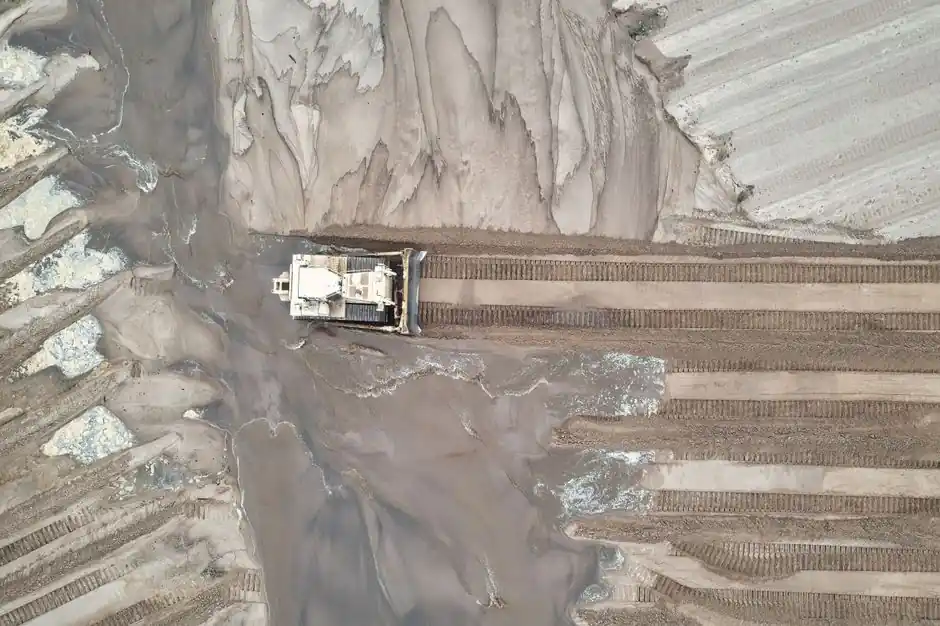
Dynamic compaction for a 10 m fill requires a design energy per unit area calculated from the deposit classification and the full treatment depth, with field verification still required [S6].
The procedure applies repeated impacts from a heavy tamper in a planned grid, producing densification below grade through transmitted shock waves rather than conventional shallow fill compaction [S1][S2][S7].
10 m Fill Depth Sets the Calculation Basis
Dynamic compaction is described as a method for densifying soils at significant depths by applying large impact energy at the ground surface [S4]. The published range is not a design allowance for every fill; it describes observed performance under site-specific conditions.
For the 10 m thickness, the design sequence is to select unit energy from the deposit classification in Table 3.4, multiply that value by the deposit thickness, and then apply the required number and spacing of impacts [S6]. In practical terms, the required impact energy per unit area increases with the depth being treated, but the material classification remains a separate input.
Dynamic compaction involves repeatedly dropping steel pounders weighing 10 to 30 tons from a significant height onto the ground surface [S5]. Compaction efficiency in dynamic compaction is governed by multiple interacting factors, including tamping energy and soil properties [S3].
Why Deposit Classification Comes First
The correct unit energy cannot be selected from a nominal depth of 10 m alone because the same thickness may contain loose sand, rubble fill, heterogeneous fill, or soils with different drainage and saturation conditions [S3][S4]. Fill classification determines the reference energy in the design procedure, and the 10 m thickness converts that reference into an area energy demand [S6].
The soil also constrains what dynamic compaction can achieve. Loose granular soils, uncontrolled fill, and fills containing large debris are suitable applications, while saturated clay is unsuitable because excess pore water restricts particle rearrangement [S4]. The best performance occurs in well-drained, high-permeability soil with low saturation [S4].
For variable fills, the engineer should identify the weakest and most heterogeneous zones before assigning one energy level to the entire 10 m deposit [S4]. A uniform design may overwork competent zones while leaving poorly compacted zones untreated, so trial work, settlement observations, and post-treatment testing should control acceptance rather than impact count alone [S2][S7].
Energy Options Compared Against Four Criteria
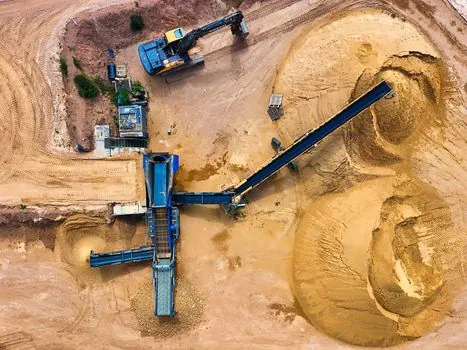
Dynamic compaction, vibroflotation, and the multi-roller compaction method used in the referenced case serve different functions, so the comparison should use treatment depth, soil suitability, field control, and imported-material demand rather than installed cost alone. [S4]
Dynamic compaction has the clearest energy-intensity pathway for deep granular densification, but it is poor in saturated clay and may need staged rest periods to dissipate pore pressure [S4]. Vibroflotation and multi-roller compaction remain credible alternatives where their depth, soil, and equipment limits fit the deposit, while dynamic compaction is better matched to large areas of loose or variable fill [S3][S4].
Impact Energy Is Only One Part of the Design
A 10 m design must specify more than total energy per unit area. The field program also needs tamper mass, drop height, impact geometry, grid spacing, number of blows, pass sequence, crater handling, and an ironing pass for surface uniformity [S3][S5]. Laboratory and field studies identify tamper mass as especially influential in stress transmission and penetration depth [S3].
The energy calculation is therefore a planning basis, not proof of performance. Impacts create craters that must be backfilled before subsequent passes, and impact energy spreads through the soil as dynamic waves [S4]. Uneven spacing can leave untreated or over-treated strips, particularly where the 10 m fill contains abrupt changes in density or composition.
Primary energy passes can be followed by a surface ironing pass to improve the upper layers and final surface uniformity [S5]. The output of a pile driver is not interchangeable with dynamic-compaction tamper energy, because the former transfers repeated driving impulses through a piling system while dynamic compaction relies on surface drops arranged by a separately engineered grid [S1][S7].
Soil Response and Failure Modes
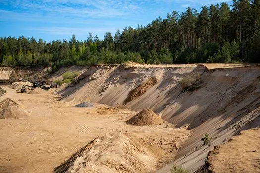
Densification depth and uniformity depend on the combined influence of applied energy, fines content, drainage conditions and initial soil state [S3]. In saturated granular soil, temporary liquefaction may rearrange particles, but the benefit depends on subsequent pore-pressure dissipation; uncontrolled application can reduce stability during treatment [S4].
Three failure modes deserve explicit checks. First, using 10 m as a universal depth rule ignores the fill classification required by the energy calculation [S6]. Second, applying the full impact energy to saturated clay is inappropriate because the method is not suitable for that condition [S4]. Third, treating completion by drop count ignores crater formation, spatial energy overlap, and heterogeneous fill, all of which can leave residual variation [S3][S4].
Noise, vibration and off-site ground vibration also require a site-specific assessment [S1]. Dynamic compaction can create substantial surface disturbance, and its environmental performance is not independent of construction energy even though it avoids the material production associated with some alternatives [S3]. A diaphragm wall grab serves a different ground-control function and should not be treated as a substitute for fill densification.
Verification and Acceptance Sequence
A defensible 10 m fill program begins with a subsurface investigation that classifies the deposit, identifies groundwater and saturated layers, and defines the target density or surface performance [S2][S7]. The designer then selects unit energy from the deposit classification, multiplies by the 10 m thickness, and translates the area demand into drop-point spacing and blows [S6].
Field verification should include a trial area, observations of crater depth and rebound, and settlement monitoring during and after treatment [S2][S4]. Where drainage is slow, piezometers can confirm pore-pressure dissipation before the next phase [S4]. The final acceptance test should be tied to the project requirement, not simply to the amount of energy delivered.
Calculated bearing-capacity gains can reach 100 to 150 kPa after dynamic compaction in suitable deposits [S4]. That is a performance range from reported applications, not an automatic guarantee for a 10 m fill. The traceable acceptance signals are the specified unit energy, approved grid and blow count, trial-area performance, measured settlement, and independent post-treatment test results [S1][S2][S6].
For a comparable shallower fill, the 6 m dynamic compaction energy selection case provides a useful calculation framework, while the 10 m case requires the thicker deposit's classification-specific unit energy and deeper verification program [S6].