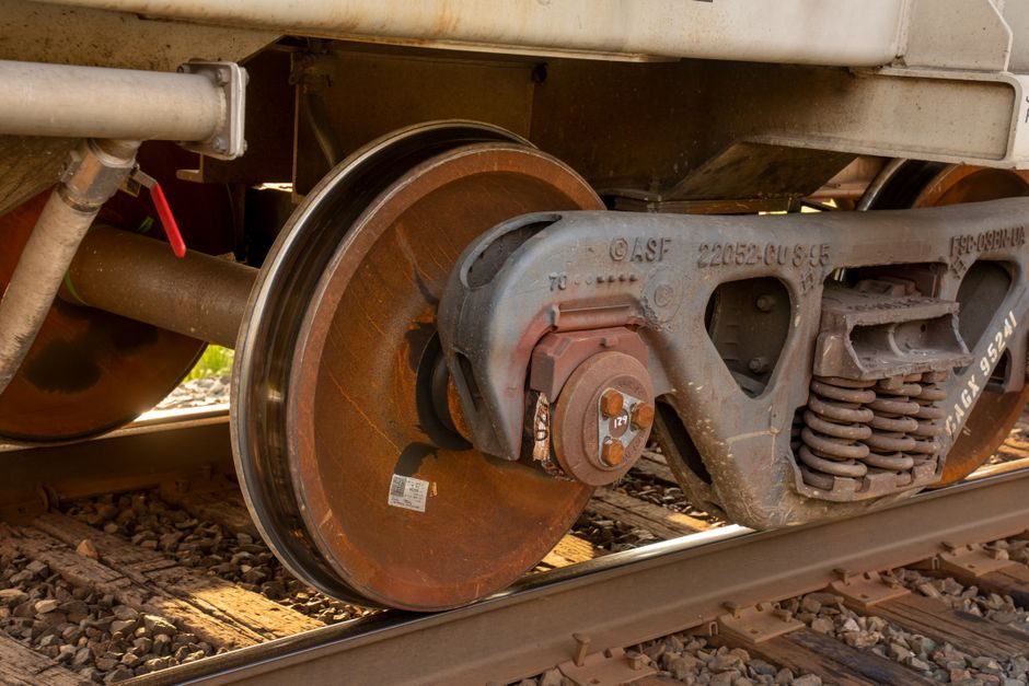
The e-axle supply squeeze in 2026 sits on three choke points: 800 V SiC inverters, sintered NdFeB rotor magnets, and the mechanical-thermal interface between gearbox housing and vehicle suspension [S1][S2]. Technavio quantifies the 2021-2026 e-axle market expansion at USD 23.53 billion added at a 30.74% CAGR, with 34% of incremental growth attributed to North America [S1].
Vehicle-side demand is split between entry-, mid-, and premium-segment passenger cars and light commercial trucks, with the same e-axle architecture reused in dual-axle configuration for C/D-segment BEVs [S2]. The FITGEN Horizon 2020 programme (Grant Agreement 824335) logged the spec-level risk register for a third-generation e-axle using a buried-permanent-magnet synchronous machine, SiC inverter, high-speed transmission, and an 800 V-compatible DC/DC stage, and assigned interface mismatch a probability of 3 and mounting-volume integration a probability of 2 on a 1-3 scale [S2].
What is actually short in 2026: SiC wafers, magnets, and LV inverter slots
SiC MOSFET bare-die allocation is the binding constraint for 800 V-class e-axle inverters; Tier-1 lines are booked into 2027 on multi-year wafer supply from a small set of qualified 150 mm foundries. Sintered NdFeB remains magnet-side critical, with Dy/Tb grain-boundary diffusion required for the 150-180 °C rotor operating envelope typical of 250 kW-class buried-PMSM e-motors. The combined effect is that inverter and magnet allocations, not gearbox or housing machining, throttle e-axle output. [S2]
The FITGEN e-axle stack matches this: buried-PMSM + SiC inverter + high-speed single-speed transmission, plus a 3.3 kW/L-class intermediate DC/DC rated to charge a 400 V pack from an 800 V station [S2]. On a risk-probability 1-3 scale (1 = not probable, 3 = mostly happening), volume and mounting-in-vehicle risk scored 2, while mismatched-mechanical and electrical-interface risk scored 3, both addressed through tight CRF/BRUSA/GKN synchronisation and periodic interface reviews [S2].
Risk register mechanics: how the 1-5 / 1-3 scores map to sourcing
Public research risk registers for e-axles and electrified trucks rate probability of occurrence 1-3 and severity in three bands (SH = slightly harmful, H = harmful, EH = extremely harmful), then prioritise mitigations by where action is required for the next product stage [S3]. This is the same scale EU OEMs apply in supplier audits, so a supplier failing the "interface" line item can lose series nomination before any dyno test runs.
For a typical 3-in-1 e-axle, the highest-probability failure modes flagged in published analyses are: (1) inverter-connector pin-out mismatch against the vehicle harness, (2) inverter cooling-port orientation conflicting with chassis rails, and (3) e-motor rotor thermal sensor harness routing being incompatible with mass-production line robots [S2][S3]. A probability-2 mounting-volume issue is normally a packaging tolerance question; a probability-3 interface issue is normally a contractual one, addressed by synchronised consortium reviews rather than retooling.
Vendor map and who actually builds 3-in-1 e-axles in 2026
Technavio's 2022 vendor list remains the public reference for who is in the market: BorgWarner (HVC motor + iDM eAxle), Dana (eSH 803 e-hub, eS20D, 3e2 gearbox), Linamar (eLin commercial and light-vehicle e-axles), Nidec (EV traction motor e-axle), Bosch (modular e-axle driving system), plus AVL, BRIST, Cardone, Continental, Daimler Truck, Dorman, GKN Automotive, Hyundai Wia, J.K. Fenner, Magna, Meritor, Schaeffler, SONA BLW, and ZF Friedrichshafen [S1]. Asia-side volume remains concentrated at Hyundai Wia, Nidec, and SONA BLW; Europe-side at ZF, Schaeffler, Bosch, Continental, and GKN; North America-side at BorgWarner, Dana, Linamar, and Magna.
For sourcing, the decision is rarely single-vendor: a passenger-car BEV programme typically dual-sources the inverter (e.g. ZF + BorgWarner) and the gearbox (e.g. Linamar + Magna), with a single-source e-motor due to magnet allocation. Dual-sourcing the inverter buys negotiating leverage on SiC allocation; single-sourcing the e-motor is forced by Dy/Tb diffusion-line capacity that no Tier-2 has yet replicated at scale [S1][S2].
Spec-to-shortage table: what changes in 2026 if you pick X vs Y
The engineering trade for a 2026 e-axle spec lines up against three decision criteria: voltage architecture, magnet type, and integration level. The comparison below is qualitative, since the public Technavio dataset sizes market growth but not per-axis share [S1].
On voltage, 800 V SiC architectures need fewer parallel MOSFETs and thinner HV cabling, but they lock the programme to the constrained SiC wafer pool; 400 V Si inverters use abundant IGBTs but add mass and copper. On magnet, sintered NdFeB delivers the power density needed for buried-PMSM machines; ferrite-assisted synchronous reluctance removes the Dy/Tb bottleneck but costs 10-15% specific power, forcing a larger stator OD. On integration, 3-in-1 modules save space and NVH cost; separate e-motor + inverter + gearbox designs let the OEM swap inverter suppliers when SiC allocation shifts. The combination the FITGEN consortium selected is buried-PMSM + SiC inverter + 800 V DC/DC, sized for A-segment single-axle and B/C/D-segment dual-axle use [S2].
Mitigations already on file from public EU R&D programmes

FITGEN's documented mitigations for the two highest-probability risks are: (a) close collaboration between CRF and BRUSA/GKN on mounting positions to absorb the probability-2 volume risk, and (b) periodic synchronisation of consortium partners to drive the probability-3 interface risk to closure [S2]. These are the same two levers procurement teams apply with their own suppliers in 2026, translated into engineering language: PFMEA reviews every 4-6 weeks, and a frozen interface-control document at the start of each e-axle build phase.
For the magnet bottleneck specifically, published risk studies for electrified heavy trucks recommend a parallel dual-track: keep the sintered-NdFeB design as the primary, and qualify a ferrite-assisted SynRM as a fallback that can drop into the same housing with a stator rewind only [S3]. The fallback is not free, but it removes the single point of failure that has caused 2024-2025 e-axle line stoppages in publicly reported OEM disclosures.
What 800 V really buys and what it does not
The 800 V architecture in the FITGEN spec enables fast-charging a 400 V on-board pack from an 800 V station via the intermediate DC/DC, with the same DC/DC also used in traction to run the motor over a wider speed range [S2]. This is a real efficiency gain — 800 V systems typically push peak charging above 250 kW on production BEVs — but it does not relax the SiC wafer constraint, since 800 V inverters are the primary SiC application.
The honest engineering trade: an 800 V e-axle does not solve supply risk, it concentrates it onto a smaller supplier pool. A 400 V e-axle on silicon IGBTs spreads risk across a larger, more commoditised base, at the cost of charging time, cable mass, and continuous-power thermal headroom. For high-volume A/B-segment programmes in 2026, this is often the rational pick; for premium C/D-segment programmes with 250+ kW DC charging commitments, 800 V is forced.
Standards and sourcing constraints that bind in 2026

No single IEC or ISO standard mandates an e-axle voltage, but the relevant product-side standards that affect sourcing are IEC 61851-1 for conductive charging (covering 800 V DC system behaviour), ISO 26262 for ASIL-rated inverter and motor control software, and ISO/SAE 21434 for cybersecurity on the CAN-FD or Ethernet link between inverter and VCU. UNECE R100 Revision 4 governs the electrical safety of the high-voltage bus, including isolation resistance and creepage/clearance on the e-axle HV connectors. Magnets are typically qualified per the customer-specific magnet spec rather than a single ISO magnet standard, and SiC MOSFETs are qualified per AEC-Q101. [S2]
For commercial-vehicle e-axles, the relevant axle-duty standards (ISO 6612, ISO 22035) and gearbox-efficiency test standards (ISO 14179) still apply unchanged from ICE axle practice, which is why commercial-vehicle e-axle programmes can carry over much of the housing and NVH validation from existing axle platforms [S1][S3].
Decision tree for a 2026 e-axle spec
Use 800 V SiC only if your segment is premium C/D passenger or your DC-charging target is above 200 kW, and only if your inverter supplier has a multi-year SiC wafer allocation in writing. Use 400 V Si if your segment is A/B or your volume target is above a few hundred thousand units a year, since IGBT allocation is de-risked. Use sintered NdFeB if your specific-power target is above 5 kW/kg at the e-motor level, and qualify a ferrite-SynRM fallback in parallel. Use a 3-in-1 integrated module if your vehicle programme is on a clean-sheet BEV platform; use a modular separate inverter + gearbox architecture if you have to share components with a PHEV programme running in parallel [S1][S2].
The expected signal to watch is a second public disclosure of an OEM e-axle line stoppage in 2026, which will indicate whether the SiC/magnet dual-track mitigation has actually held. For further context on the broader e-axle supply chain, the 2026 e-axle supply chain assurance analysis covers the magnet-to-gigafactory math in detail, while the electric pallet truck voltage-band spec map shows how the same 400 V vs 800 V decision plays out in adjacent industrial-vehicle segments. The 2026 pressure-vessel selection spec map is unrelated mechanically but illustrates the same code-driven sourcing logic that e-axle programmes are now adopting for inverter safety cases.
The underlying component specifications are covered under dc power supply, switching power supply, and industrial ups.