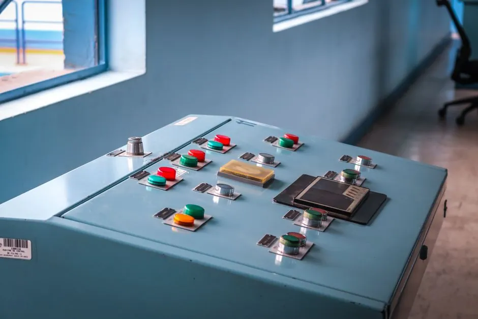
An electromagnetic brake is a friction device held closed by spring force and released by a DC coil, so the engineering question is not whether it can hold a load, but how fast, how often, and under what voltage envelope it can be cycled without thermal runaway.
Published industrial envelopes span 2.5 Nm to 4,000 Nm of static torque, 12 VDC to 200 VDC coil supply, Class F insulation as the typical minimum, and maximum friction-surface speeds of 1,800-3,600 rpm for general-purpose units and up to 10,000 rpm for high-speed executions [S1][S10].
Operating Envelope and Coil-Side Specs
The coil-side envelope is where selection starts. A representative 24 VDC single-disc family covers static torque from 6 Nm up to 400 Nm, dynamic torque from 5 Nm to 320 Nm, coil power from 11 W to 60 W at 20 degrees C no-load, and a maximum speed of 1,800 rpm, with weight scaling from 0.28 kg to 10.5 kg across the same range [S9]. A second manufacturer data set for the same voltage class lists 0.32 kg to 12.2 kg, a 0.5-40 kgf-m static range, and identical 24 VDC rating [S5]. The fact that two vendors converge on 1,800 rpm and 24 VDC for a 400 Nm class is the working signal that the DC 24V single-disc format is now a de facto commodity in the small/medium range.
For larger holding duties, the envelope widens. One vendor publishes a 2.5-4,000 Nm torque range, 12-200 VDC supply, Class F insulation, and a 68-333 mm brake diameter span with a 3,600 rpm ceiling, all on a 50 Hz foundation [S1]. A separate series rated 42-460 V wide-input and 3-1,350 Nm torque adds CE certification, ROHS and REACH compliance, and F-grade insulation as documented supplier claims [S8]. Holding-torque vs. shaft-size mapping on a 5-1,000 Nm spring-applied single-disc family shows 8-65 mm shaft range and 10-280 W coil dissipation at 24-205 VDC [S3].
Static vs. Dynamic Torque, and Why the Ratio Matters
Static torque is what holds a stopped load; dynamic torque is what a brake can deliver while slipping, and the gap between them tells you the thermal story. In the 24 VDC disc family, the static-to-dynamic ratio sits at roughly 1.2:1 across the line: 6 Nm static / 5 Nm dynamic, 25 Nm / 20 Nm, 100 Nm / 80 Nm, 400 Nm / 320 Nm [S5][S9]. That ratio means you cannot assume the nameplate static number is available under slip, and you must derate the working dynamic load by the same 15-20 percent margin when sizing against an E-stop kinetic energy budget.
For continuous-slip tension control, the static number is largely irrelevant and the dynamic rating plus thermal capacity is what governs. A 100-600 ms engagement window is typical for larger spring-applied units, and release time runs 30-200 ms depending on size and spring pre-load [S10]. Engineers specifying a high-cycle stop-start application should treat the dynamic figure plus thermal capacity (kJ or Ws) as the binding constraint, not the headline static torque.
Single-Disc Dry, Multi-Disc Wet, and One-Face Brake: Form-Factor Match

Three physical form factors dominate the industrial catalogue, and each maps to a different duty. Spring-applied single-disc dry brakes with two friction surfaces are the workhorse for E-stop and park-hold on motors from sub-1 kW up to roughly 30 kW, with typical envelopes of 5-1,000 Nm holding torque at 24-205 VDC [S3]. ATO's 6-400 Nm, 24 VDC series fits that pattern, with six frame sizes, 1,800 rpm ceiling, and weights from 0.28 kg to 10.5 kg [S9].
Multi-disc wet executions are the choice for oil-immersed, high-cycle dynamic duty. A published multi-disc wet series lists 24-3,600 Nm torque in oil, 12-115 mm bore, 80-250 mm OD, and 29-80 mm axial length, with the explicit note that the magnetised disc stack is only suitable for oil running and oil viscosity must be observed [S2]. A separate dry-run one-face brake on the same product line covers 2-600 Nm, 8-80 mm bore, 62-290 mm OD, and 21-103 mm length [S2]. The dry/wet split is the decision gate: oil-bath multi-disc for high-cycle slip, dry single-disc for park-hold and E-stop, and one-face dry units for compact mid-torque builds.
Insulation, Voltage, and Certification Gates
Class F insulation (155 degrees C) is the published baseline for industrial-grade electromagnetic brakes, and it is paired with epoxy resin-bonded coils for vibration resistance on at least one vendor line [S1]. Coil voltage is not a free choice: 12-200 VDC covers the standard DC range, with 24 VDC the dominant pick in published single-disc families [S1][S5][S9]. Wide-input 42-460 V executions exist for plants standardising on rectified AC or a common DC bus, with 3-1,350 Nm torque on the same frame [S8].
Certification signals to look for in published datasheets include CE marking, ROHS and REACH compliance, and F-grade insulation withstand testing, all of which appear on at least one manufacturer's published line [S8]. Higher-tier documentation such as type-test certificates for the China bridge and gantry sector appears on the same datasheet, indicating that for crane and hoist applications the supplier paperwork, not just the electrical spec, is part of the gate [S8]. The clutch-brake family sits adjacent and shares the same coil-side architecture, which is why combined clutch-brake units are a common machine-tool option.
Speed, Thermal Capacity, and Failure Modes
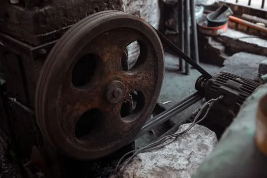
Maximum friction-surface speed is the single most over-looked gate. Standard industrial dry brakes are published at 1,800-3,600 rpm, and high-speed executions reach 10,000 rpm [S10]. Exceeding the published maximum speed risks frictional fade, face glazing, and unpredictable torque decay, because the heat-sink capacity of the friction pair was sized for a specific surface-velocity envelope.
Thermal capacity, measured in kJ or Ws, is the second gate. The same parameter reference cites continuous slip rating in Ws, with the practical reading that the brake must dissipate, not just absorb, the heat of each cycle within the inter-event interval [S10]. A brake resistor on a VFD-driven motor handles regenerated electrical energy; it does not handle mechanical deceleration energy, which is the brake's job. Concretely, if the cycle time is shorter than the thermal recovery time, expect face temperature to climb into the Class F ceiling and torque to drop. A static-to-dynamic ratio near 1.2:1 across sizes is a tell that the design margin between holding and slipping is narrow by intent, and that thermal derating under continuous slip is expected [S5][S9].
Who Should Pick What: A Selection Shortlist
Pick a 24 VDC single-disc dry brake in the 6-400 Nm range with 1,800 rpm ceiling when the duty is E-stop and park-hold on a general-purpose induction motor, where 0.5-12 kg frame weights and 11-60 W coil dissipation make panel integration simple [S5][S9]. Pick a 12-200 VDC, 2.5-4,000 Nm, Class F spring-applied disc with a 68-333 mm diameter for hoist, crane, and large gearmotor hold, where 3,600 rpm ceiling is acceptable [S1]. Pick a wide-voltage 42-460 V, 3-1,350 Nm execution with CE/ROHS paperwork when the plant bus is mixed AC/DC and the procurement gate is documentation completeness [S8].
Do not pick a dry single-disc for continuous-slip tension control, since the thermal envelope will collapse within minutes; pick a multi-disc wet unit in the 24-3,600 Nm range and accept the oil-viscosity design constraint [S2]. Do not pick a multi-disc wet unit for a food-grade or clean-room build, since the oil bath rules it out. Do not pick a 1,800 rpm dry disc for a high-speed spindle above that ceiling; overspec to a 3,600 rpm or 10,000 rpm execution [S10]. Procurement engineers cross-checking duty-cycle math should also review the related industrial-spec digest for the wider 2026 component-procurement signal stack.
Selection Checklist You Can Hand to a Vendor
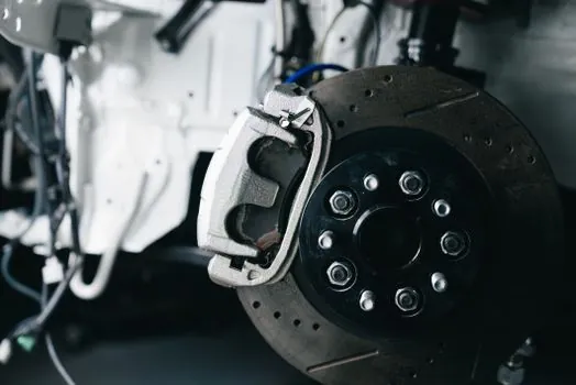
Confirm the static-to-dynamic ratio, the maximum speed in rpm, the coil voltage and wattage at 20 degrees C, the insulation class, the thermal capacity in kJ or Ws, the engagement and release times in ms, and the certification paperwork (CE, ROHS, REACH, type-test) before signing a purchase order [S1][S8][S10]. One supplier's wide-voltage 42-460 V, 3-1,350 Nm, F-grade, CE/ROHS line is a useful benchmark against which to compare alternatives on documentation depth, not just headline torque [S8]. For the upstream electrical architecture, note that a flow meter or pressure transmitter on the same machine has entirely different EMC and insulation constraints, so do not assume a vendor's instrument-side certifications transfer to a brake quote.