A brake resistor, also called a braking resistor or dynamic braking resistor, is a high-power resistive element that converts the surplus electrical energy regenerated by a decelerating motor into heat. It is the dissipation half of a dynamic braking circuit: a brake chopper transistor inside the variable frequency drive (VFD) monitors the DC bus voltage and, when a falling load pushes that voltage above a set threshold, switches the resistor across the bus to bleed the energy away.
Brake resistors are deceptively simple components that are easy to undersize. Choosing one correctly is a two-axis problem: the resistance in ohms sets the peak braking power and must never fall below the value the drive can switch, while the power rating in watts is governed by the application duty cycle and the resistor thermal mass. This guide separates those two axes and reduces them to working formulas.
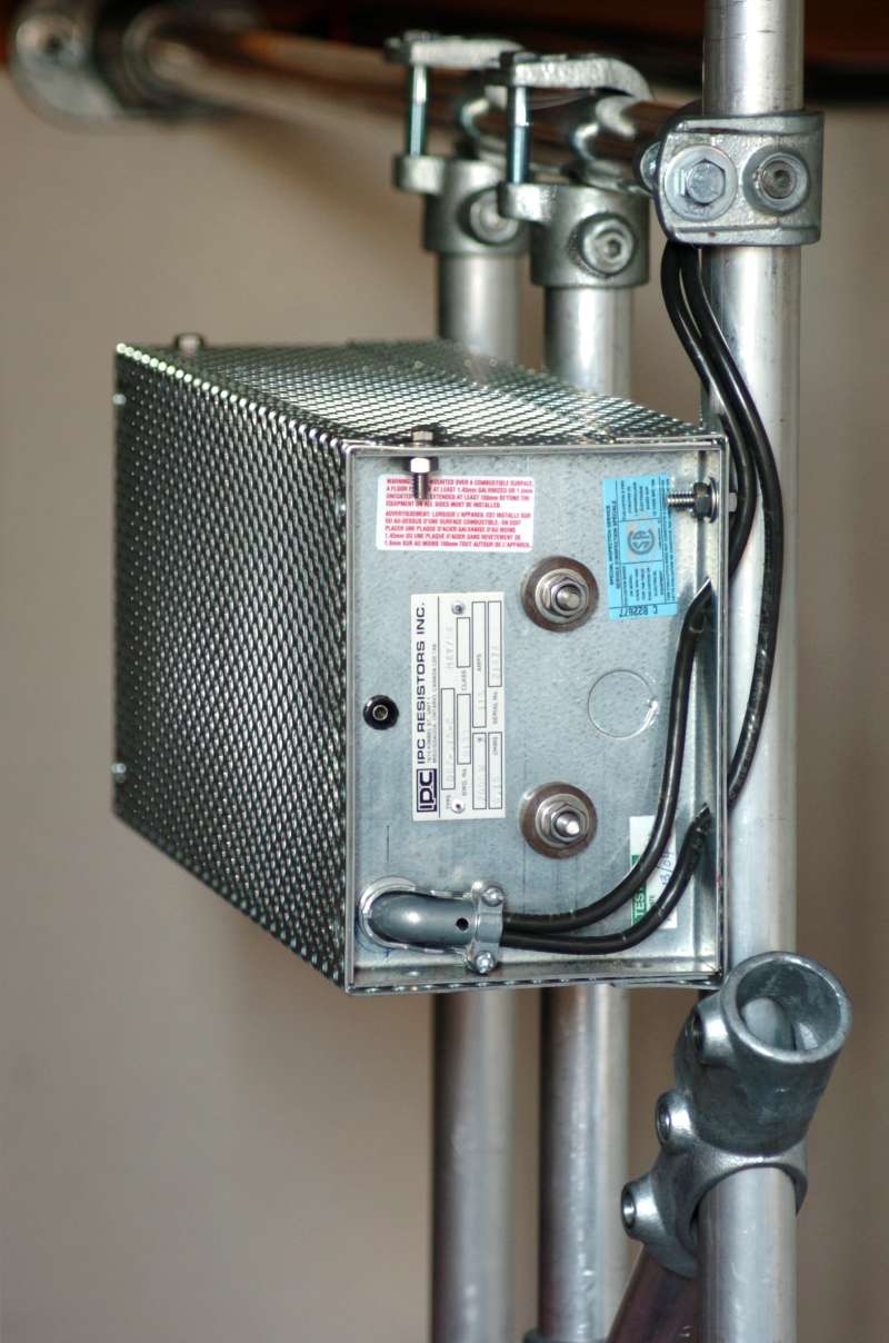
Photo: Glogger at English Wikipedia, CC BY-SA 3.0, via Wikimedia Commons
This guide is written for industrial purchasing engineers and machine designers specifying brake resistors for VFD, servo, crane, and traction applications. It covers 6 chapters from the physics of dynamic braking, the four resistor construction families, the ohm and wattage sizing formulas, key spec parameters, to a structured selection sequence, with 7 FAQs and maker comparisons. Parameter ranges reference IEC 60115 (fixed resistors), IEC 61800-5-1 (adjustable speed drive safety, the standard that since February 2020 also serves as UL 61800-5-1 in North America, superseding the withdrawn UL 508C), and published data from drive and resistor manufacturers.
Chapter 1 / 06
What is a Brake Resistor
A brake resistor is a resistive load that absorbs and dissipates the regenerative energy produced when an electric motor decelerates or holds back an overhauling load. In normal motoring, energy flows from the mains, through the drive, into the motor, and out as mechanical work. When the drive commands a deceleration faster than friction and windage would naturally produce, or when gravity drives an elevator car, hoist, or conveyor downward, the motor reverses its role and behaves as a generator. The kinetic energy stored in the rotating mass, or the potential energy of the descending load, is converted back into electrical energy and pushed into the drive intermediate DC bus.
The DC bus of a standard voltage-source drive is a bank of electrolytic capacitors fed by a diode rectifier. A diode rectifier is a one-way street: it can pass energy from the mains to the bus but cannot return energy to the mains. With nowhere else to go, the regenerated energy charges the bus capacitors and the bus voltage climbs. If the rise is not arrested, the drive trips on a DC bus overvoltage fault, and in a severe case the capacitor voltage rating is exceeded and the capacitors fail. The brake resistor, switched by the brake chopper, is the controlled escape valve that converts the surplus to heat before either happens.
The physics is the same as the friction brake on a car, only the energy path differs. A car turns kinetic energy into heat at the brake disc through friction; a drive turns it into heat in a resistor through Joule heating, P equals I squared times R. Because all the braking energy ends up as heat in the resistor element, a brake resistor is, by construction, a deliberately inefficient device: its entire job is to waste energy safely and at a controlled rate. This is why heat dissipation, thermal mass, and surface temperature dominate its engineering, far more than the precision and stability concerns that dominate a sensing resistor.
Historically, resistor braking grew out of railway and crane practice, where banks of cast-iron grid resistors had dissipated traction braking energy since the early twentieth century. The modern compact brake resistor arrived with the solid-state variable frequency drive in the 1980s, when the IGBT brake chopper made it practical to pulse a resistor across the DC bus thousands of times per second. Today brake resistors range across roughly six orders of magnitude of power, from a few tens of watts protecting a small servo amplifier to multi-megawatt grid banks on locomotives and large mine hoists, and the selection task is to map a specific load cycle onto the right construction, ohms, and wattage.
It is worth fixing the vocabulary early. Dynamic braking is the general method of converting regenerated energy to heat in a resistor. The brake chopper, brake transistor, or brake unit is the switching electronics; on small and mid-size drives it is built in, while large drives use a separate brake chopper module. Rheostatic braking is the older term for the same idea on DC and traction machines. Regenerative braking, by contrast, returns the energy to the mains and does not use a resistor at all; it is the alternative discussed in Chapter 6.
Chapter 2 / 06
Resistor Construction Types
Brake resistors are classified first by how the resistive element is built, because construction sets the achievable power, the enclosure options, and the cost. Four families cover almost all industrial drive applications: wirewound, aluminium-housed, edgewound strip, and steel grid or expanded mesh. The table below compares them on the engineering metrics that drive selection.
Wirewound resistors use an open helical winding of a resistance alloy such as nickel-chromium or copper-nickel wound on a tubular ceramic former, often coated in vitreous enamel for protection. The open helix cools quickly and the construction is shock resistant, which suits the small, frequently cycled drives found on conveyors, packaging machines, and servo axes. They are the lowest cost family and the workhorse of small and mid drives, but the bare element runs hot and is usually mounted unenclosed inside a ventilated cabinet, so clearance and airflow must be designed in.
Aluminium-housed resistors clamp a wirewound element inside an anodised aluminium extrusion that acts as a heat sink. The anodised aluminium is non-corrosive, light, and an excellent heat conductor, and the closed housing achieves high ingress protection, commonly IP54 or IP65, with good vibration tolerance. Nominal ratings typically span roughly 42 W to 4,350 W. This family is the natural choice when the resistor must be wall mounted outside the cabinet, or installed in a dusty, damp, or washdown environment, at the cost of a higher per-watt price than a bare wirewound element.
Edgewound strip resistors wind a stainless-steel tape on edge over tubular ceramic insulators. Winding the strip on edge gives a large surface area in a compact body and handles medium current well, with good shock resistance. Edgewound elements bridge the gap between small wirewound units and large grids, covering roughly tens of watts to the low tens of kilowatts continuous, and are common on machine tools and mid-power process drives. Cressall, for example, builds its DBR edgewound family up to the 25 kW continuous band.
Steel grid and expanded-mesh resistors stack punched steel sheets, or a low-inductance expanded-mesh element, on insulated steel rods between end frames, the descendant of classic traction resistor banks. They handle the heaviest dissipation, from tens of kilowatts up into the megawatt class, and are specified for cranes, hoists, locomotives, dynamometer test rigs, and load banks. Enclosures are offered in pre-galvanised mild steel for indoor use, or 304 and 316 stainless steel for marine, offshore, and corrosive environments. Cooling may be natural convection for moderate duty or forced air for sustained high power.
Chapter 3 / 06
The Dynamic Braking Circuit
To size and apply a brake resistor correctly you have to understand the circuit it lives in. The dynamic braking circuit has three parts working together: the DC bus, the brake chopper, and the resistor. The chopper is the decision maker; the resistor is the heater; the bus voltage is the signal that triggers the whole thing.
The DC bus voltage of a diode-rectified drive sits at roughly 1.35 times the AC supply line voltage under load, rising toward 1.41 times at light load, because the rectifier charges the bus capacitors to near the peak of the line-to-line waveform. A 400 V three-phase supply therefore produces a nominal bus of about 540 to 560 V, and a 480 V supply about 650 to 680 V. The brake chopper turn-on threshold is deliberately set above this nominal level so that the chopper fires only when regenerated energy is genuinely raising the bus, not during normal motoring. Typical turn-on thresholds fall near 380 to 400 V DC on a 230 V drive and near 750 to 820 V DC on a 400 to 480 V drive, with some designs holding the resistor on until the bus drops back below a slightly lower release level to give hysteresis.
The chopper itself is a power transistor, almost always an IGBT on modern drives, in series with the brake resistor across the DC bus. When the bus voltage exceeds the turn-on threshold the chopper switches the resistor in, the bus discharges through the resistor, and when the voltage falls back the chopper switches off. In practice the chopper pulse-width modulates, rapidly turning on and off, to hold the bus near the threshold and regulate the dissipated power smoothly. The maximum current the chopper transistor can carry is the hard limit that sets the minimum resistance you are allowed to fit, the subject of the next chapter.
Resistor braking is one of four electrical braking strategies a drive can use, and choosing among them is part of system design. The table below contrasts them.
Braking Method
Where Energy Goes
Relative Cost
Best For
Resistor (dynamic) braking
Heat in external resistor
Low
Occasional or low-duty fast stops
DC injection braking
Heat in motor windings
Very low
Final stop at low speed, no holding
Flux braking
Heat in motor (raised flux)
Very low
Modest extra braking, no resistor
Regenerative (line-regen)
Returned to the AC mains
High
Frequent high-power braking, recovery
DC injection braking applies a DC current to the stator windings to create a stationary magnetic field that drags the rotor to a halt, dumping the energy as heat in the motor itself; it needs no resistor but produces no controlled holding torque and stresses the motor thermally. Flux braking raises the motor magnetising flux during deceleration so more energy is lost in the machine, adding a little braking without external hardware. Regenerative braking uses an active front end to invert the bus energy back onto the mains; it recovers energy and generates no heat, but costs far more and needs harmonic and EMC filtering. The brake resistor remains the default for the large majority of drives because it is cheap, simple, and reliable for the occasional or moderate braking that most machines actually need.
Chapter 4 / 06
Sizing: Ohms and Watts
Sizing a brake resistor is a two-step calculation: first find the resistance in ohms, which is bounded below by the drive, then find the power rating in watts, which is bounded below by the application duty cycle. Treating these as separate problems is the single most useful habit in brake resistor selection, because the two limits come from different places and a resistor that satisfies one can still fail the other.
Step one, the resistance. The ohmic value sets how much braking power flows at a given bus voltage, through the simple relation P equals V squared divided by R. The lower the resistance, the higher the current and the higher the braking power. But the chopper transistor has a maximum current rating, so there is a minimum resistance below which the chopper is overstressed. That minimum is:
R(min) = V(bus)² / P(peak), where V(bus) is the chopper turn-on voltage and P(peak) is the maximum braking power the drive can switch.
For example, a 400 V drive with a chopper turn-on near 780 V DC that must absorb a 20 kW braking peak needs at least 780 squared divided by 20,000, which is about 30 ohms. Fitting less than that risks tripping the chopper overcurrent or damaging the transistor. Because the published element resistance carries a tolerance, often plus a few percent, and rises further as it heats due to the positive temperature coefficient, a margin is applied: a widely used rule selects the working resistance at about 1.2 times R(min). Choosing a higher resistance is always electrically safe; it simply reduces the achievable braking torque in proportion, so you trade braking speed against headroom.
Step two, the power rating. The wattage is set by how much energy must be dissipated and how often, not by the peak. Begin with the braking energy per stop. For a rotating inertia that is the kinetic energy E equals one half times J times omega squared, where J is the system inertia referred to the motor shaft and omega the angular velocity; for an overhauling vertical load it is the potential energy E equals m times g times h released per cycle. The continuous power rating then follows from the duty cycle:
P(continuous) ≈ E(braking) / t(cycle) = P(peak) × duty cycle, where duty cycle = braking time / total cycle time.
The duty cycle is the lever. The table below shows how the same peak braking maps to very different continuous ratings depending on how often the machine brakes.
Application Pattern
Typical Duty Cycle
Continuous Rating vs Peak
Example
Occasional stop
~10%
~0.1 × peak
Fan, pump stopped once per shift
Regular cyclic stop
~20 to 30%
~0.2 to 0.3 × peak
Conveyor, indexing machine
Heavy positioning
~50%
~0.5 × peak
Crane or hoist cycling up and down
Continuous control
~100%
~1.0 × peak
Web unwinder, tension control
Two refinements matter. First, resistors carry an intermittent overload capability far above their continuous rating, because the element and any heat sink store heat during the braking pulse and shed it during the cool-down. Manufacturers publish overload curves and values such as P6, P25, and P40, where the number is the cumulative seconds of operation within a two-minute window; sizing on the intermittent curve plus the real duty cycle avoids gross oversizing. Second, always add a thermal margin of about 25 to 50 percent on top of the calculated continuous power to cover elevated ambient temperature, thermal cycling fatigue, and aging.
Chapter 5 / 06
Key Specification Parameters
Reading a brake resistor datasheet means checking a short list of parameters against the drive and the duty. Unlike a precision resistor, accuracy and stability barely matter here; thermal capacity, ohmic limits, and protection dominate. The parameters below are the ones that actually decide a selection.
Resistance value and tolerance. The ohmic value must sit at or above the drive minimum from Chapter 4. Brake resistors use loose, asymmetric tolerances because only the lower bound is dangerous: typical published tolerances are around minus 0 plus 5 percent on small wirewound units and minus 0 plus 10 percent on larger edgewound and grid units, deliberately allowing the resistance to run high rather than low. The temperature coefficient is positive, so the hot resistance is higher than the cold value, which is conservative for chopper protection.
Continuous power and intermittent overload. The continuous watt rating is the steady dissipation the element can sustain at rated ambient without exceeding its temperature limit. The intermittent ratings (P6, P25, P40 style values, or an overload curve) describe short-burst capability and are the figures to size against for cyclic braking. The thermal time constant, often in the order of tens of seconds or more for large elements, tells you how long a burst the resistor can absorb before its temperature stabilises.
Maximum surface and element temperature. Bare wirewound and edgewound elements routinely reach 200 to 300 degrees Celsius or hotter at full load. This governs clearance to wiring and adjacent components, cable insulation rating at the terminals, and whether a guard is required to prevent burns. Aluminium-housed units run cooler at the case but still need airflow.
Ingress protection and enclosure. IP rating ranges from open IP00 and IP20 elements for in-cabinet use, through IP54 and IP65 aluminium-housed units for wall mounting, to enclosed grid banks in galvanised or stainless steel for outdoor, marine, and offshore duty. Match the IP rating to the installation environment, not to convenience.
Thermal protection device. Most industrial brake resistors include a thermal cutout, a normally closed klixon or a temperature switch, that opens on over-temperature. This contact must be wired into the drive enable or fault circuit so that an overload, a stuck chopper, or a blocked airflow trips the drive rather than continuing to heat the resistor toward a fire. Treat the absence of a usable thermal contact as a serious negative in selection.
Inductance and connection. Steel-grid braking benefits from low-inductance (expanded-mesh) construction so the chopper does not see voltage spikes when it switches. Connection style ranges from flying leads and terminal blocks to busbar studs on large banks. Cable length and cross-section between drive and resistor are specified by the drive maker to keep loop inductance and voltage drop within limits.
The table below summarises how these key specifications scale across the four construction families, as a quick cross-check during selection.
Parameter
Wirewound
Aluminium-housed
Edgewound
Steel grid
Continuous power
0.05 to 5 kW
0.04 to 4.3 kW
0.04 to 25 kW
10 kW to 1 MW+
Typical tolerance
−0/+5%
−0/+5%
−0/+10%
−0/+10%
IP rating
IP00 to IP20
IP54 to IP65
IP20 to IP23
IP00 to IP65
Relative cost per watt
Low
Medium
Medium
Low (at scale)
Chapter 6 / 06
Selection Decision Factors
To turn the preceding chapters into a specific part number, work through the sequence below. The order matters: each step constrains the next, and most selection errors come from jumping to a catalog number before the drive limits and the duty cycle are pinned down. These eight steps double as an RFQ template.
Confirm the drive limits first: read the drive manual for the minimum resistance it allows and the brake chopper turn-on voltage and current rating. These two numbers are non-negotiable hard limits and everything else is built around them. If the drive has no built-in chopper, add an external brake unit sized to the same logic.
Set the resistance: compute R(min) = V(bus)² / P(peak), then select the working value at about 1.2 times R(min), at or above the drive minimum. Higher is safe; below the minimum is forbidden.
Quantify the braking energy: calculate the energy per cycle from inertia (½Jω²) for flywheel and rotating loads, or potential energy (mgh) for vertical overhauling loads such as hoists and elevators, including the worst-case stop.
Determine the duty cycle: establish braking time, cycle time, and stops per hour. This sets the continuous rating from the peak via P(continuous) ≈ P(peak) × duty cycle, and is where most undersizing happens.
Pick the power rating with margin: size against the intermittent overload curve for the duty, then add 25 to 50 percent thermal margin for ambient temperature, cycling, and aging.
Choose the construction and enclosure: wirewound or aluminium-housed for small drives, edgewound for mid power, steel grid for the heaviest duty. Match IP rating to the location: in-cabinet IP20, wall mount IP54 or IP65, outdoor or marine stainless enclosure.
Verify thermal protection and installation: confirm a thermal cutout contact is present and wire it into the drive fault circuit. Mount convection-cooled units with fins vertical, provide clearance and airflow, and keep the surface away from cabling and heat-sensitive parts.
Decide resistor versus regeneration: if braking is frequent and high power, compare the lifetime cost of a brake resistor (wasted energy, heat removal) against an active-front-end regenerative drive that returns energy to the mains. For occasional braking the resistor wins on cost and simplicity.
One dimension that is easy to overlook is serviceability and sourcing: whether the resistor is a stocked standard part or a custom build with a long lead time, whether the thermal contact and element are field replaceable, and whether the supplier can match the drive maker published minimum ohms and chopper rating. For a drive under warranty, the drive maker matched resistor or brake unit (ABB, Siemens, Rockwell Automation, Schneider Electric, KEB, Eaton) is the lowest-risk path; specialist resistor makers such as Cressall, Danotherm, Frizlen, REO, Ohmite, Vishay, and Post Glover then compete on price, thermal headroom, and enclosure options once the electrical limits are fixed.
FAQ
What does a brake resistor actually do in a variable frequency drive?
A brake resistor gives regenerated energy somewhere to go. When a motor decelerates faster than friction allows, or lowers an overhauling load, it runs as a generator and pumps current back into the drive DC bus, raising the bus voltage. Once the bus passes the brake chopper turn-on threshold (roughly 380 to 400 V DC on a 230 V drive, about 750 to 820 V DC on a 400 to 480 V drive), the chopper IGBT switches the resistor across the bus and the surplus kinetic or potential energy is converted to heat. Without the resistor the drive trips on DC bus overvoltage or, worse, ruptures the bus capacitors.
How do I calculate the resistance value in ohms?
The ohmic value sets the braking power at a given bus voltage, so it is bounded below, not above. The minimum resistance is R(min) = Vbus squared divided by P(peak), where Vbus is the chopper turn-on voltage and P(peak) is the largest braking power the drive can switch. Going below R(min) forces a peak current that exceeds the chopper transistor rating and damages the drive. Because of resistance tolerance and the positive temperature coefficient of the element, apply a margin: a common rule is R(selected) equals about 1.2 times R(min). Higher resistance is always electrically safe; it simply lowers the available braking torque in proportion.
How do I calculate the wattage rating?
Wattage is driven by the duty cycle, not the peak. First find the braking energy per cycle from the kinetic energy J times omega squared divided by 2 for rotation, or m times g times h for an overhauling vertical load. The continuous rating is roughly the braking energy per cycle divided by the total cycle time, which equals the peak braking power multiplied by the duty cycle (braking time divided by cycle time). A short stop once per minute may need only a 10 percent duty resistor, while a crane or unwinder running 50 to 100 percent duty needs near full continuous rating. Resistors also carry a much higher intermittent rating because the element acts as a thermal flywheel, so manufacturers publish overload curves and values such as P6, P25, P40 (cumulative seconds of use within a two-minute window); size on that curve plus a 25 to 50 percent thermal margin.
What resistor construction types exist and where is each used?
Four constructions dominate. Wirewound resistors (helical alloy wire on a ceramic or vitreous-enamel former) cover small drives from roughly 0.6 to a few kW. Aluminium-housed resistors clamp a wirewound element into an anodised heat-sink case, reaching IP54 or IP65, vibration tolerance, and ratings up to several kilowatts. Edgewound resistors (stainless tape wound on edge over ceramic insulators) handle medium current in a compact body, typically tens of watts to tens of kilowatts continuous. Steel grid or expanded-mesh resistors stack punched steel sheets and serve the heaviest duties, from tens of kilowatts to the megawatt class on traction and crane systems.
What IP rating and mounting do I need for an outdoor or harsh location?
Inside a ventilated control cabinet an open IP00 to IP20 wirewound or edgewound element is acceptable, but its surface can exceed 200 to 300 degrees Celsius, so allow clearance from cabling and provide airflow. For wall mounting in dusty, wet, or washdown areas choose an aluminium-housed unit at IP54 or IP65, or a stainless-steel-enclosed grid resistor (304 or 316) for marine and offshore service. Always orient convection-cooled resistors so the fins run vertically, keep them away from heat-sensitive components, and verify the thermal-cutout or klixon contact is wired into the drive enable circuit so an overload trips the drive rather than starting a fire.
When should I use a brake resistor versus a regenerative line-side unit?
A brake resistor burns the regenerated energy as heat: it is the cheapest, simplest, and most robust option, and it is the right choice for occasional or low-duty braking such as stopping a fan, pump, or conveyor. A regenerative or active-front-end drive returns the energy to the mains instead of wasting it, which pays back when braking is frequent and high power, for example a continuously cycling hoist, centrifuge, or test rig, or where the heat itself is a problem. The crossover is governed by energy recovered per year versus the higher capital cost and harmonic and EMC filtering that an active front end requires.
Which manufacturers make industrial brake resistors?
Specialist resistor makers include Cressall (ES wirewound, DBR edgewound, and HPR steel-grid families), Danotherm (convection, forced-air, and water-cooled aluminium-housed and stainless ranges), Frizlen, REO, Ohmite, Vishay, and Post Glover. Major drive vendors also sell matched resistors and brake units under their own part numbers, including ABB, Siemens, Rockwell Automation (Allen-Bradley PowerFlex), Schneider Electric, KEB, and Eaton. For a drive under warranty, ordering the drive maker's matched resistor or at least confirming the published minimum ohms and chopper rating is the safest path; third-party specialist resistors then compete on price, thermal headroom, and enclosure options.