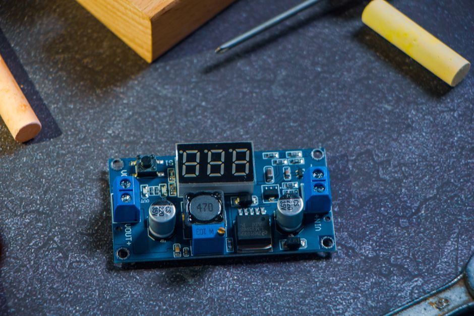
An electronic load is a programmable DC sink rated by voltage, current, and power (commonly 60 W bench units up to multi-kW rack cabinets), used to discharge a source under controlled constant-current, constant-voltage, constant-resistance, or constant-power modes [S1].
A function generator is a programmable AC/arbitrary voltage source rated by frequency range, sample rate, and output impedance, used to stimulate a device-under-test with sine, square, triangle, ramp, or arbitrary waveforms [S1].
Definition and Operating Quadrant
Both instruments sit on a bench, both are programmable over USB/LAN/GPIB, and both are sold as "general-purpose test gear," which is exactly why buyers confuse them on purchase orders [S1].
The four-quadrant VI plot makes the difference mechanical: quadrant I and III (positive or negative voltage with positive or negative current flowing out of the instrument) is the source side—where a function generator lives. Quadrants II and IV (current flowing back into the instrument) is the sink side—where an electronic load lives. If your DUT is a battery, PV panel, fuel cell, or DC power supply output, you need a sink; if your DUT is an amplifier input, filter, or ADC, you need a source.
Core Spec Bands to Compare
Electronic loads are specified by maximum input voltage (commonly 60 V to 1000 V models), maximum sink current (1 A to 1200 A per channel), continuous dissipation in watts, and slew rate in A/µs for dynamic load steps; function generators are specified by maximum output frequency (1 MHz to 6 GHz RF variants), DAC sample rate (50 MSa/s to 5 GSa/s on arb models), vertical resolution in bits (8 to 16), and output amplitude into 50 Ω (typically 1 mVpp to 20 Vpp) [S1].
Compare side by side: an electronic load at 60 W/60 V/30 A bench class costs a fraction of a 1 MHz arb function generator with similar build quality, because the load dissipates heat while the function generator produces clean edge rates. A 2-channel function generator is not a load and cannot sink current; a 16-channel modular load is not a source and cannot drive a waveform into a DUT [S1].
Who Each Instrument Is For
An electronic load is specified by power-electronics engineers characterizing battery discharge curves, DC-DC converter cross-load regulation, MPPT tracker efficiency, or fuse/breaker trip behavior; the instrument forces a known current or resistance while the engineer logs voltage decay [S1].
A function generator is specified by analog/RF engineers validating op-amp bandwidth, ADC linearity, filter response, or communication-protocol stimulus, where the instrument produces a known waveform while the engineer logs the DUT's response. If the test plan contains words like "discharge," "solar curve," or "hold-up time," the load wins. If the plan contains "Bode plot," "PLL lock," or "eye diagram," the function generator wins.
Selection Criteria by Use Case
For a single-bench lab covering both roles, spec an electronic load first when 70 percent of the work is power-source validation, and spec a function generator first when 70 percent of the work is analog-circuit stimulation; buying one of each at the 60 W / 25 MHz tier is the standard entry path [S1].
Multi-channel modular loads (4- to 16-channel) are the right answer for parallel-cell battery formation and PCBA production ATE, where each channel needs independent CC/CV/CR/CP setpoints and sequencing; a function generator cannot replace this because it cannot absorb current at all [S1]. Bench multimeters, source measure units (SMUs), and DC power supplies each overlap one quadrant but none overlap the sink-only or source-only role of these two instruments. A useful adjacent reference for sizing DC source bench gear is the programmable DC power supply price 2026 cost band map, which uses the same watt-tier and channel-count logic.
Limits, Failure Modes, and Integration Traps
Electronic loads fail most often from undersized heat-sink rating: a 60 W continuous rating does not mean 60 W of pulsed power, and pulling 30 A at 60 V into a CC mode for hours will thermal-limit a cheap chassis; spec for continuous, not peak [S1].
Function generators fail most often from output impedance mismatch: the standard 50 Ω source termination assumes the DUT is also 50 Ω-terminated or high-impedance, otherwise amplitude halves and reflections corrupt rise-time measurements. Dynamic load steps on an electronic load require careful sense-lead routing; remote-sense terminals are not optional at currents above 5 A, or the lead-resistance drop will be counted as DUT voltage and the test will pass when it should fail.
Standards and Sourcing Anchors
Neither instrument is governed by a single product safety standard unique to the category; they fall under general lab-instrument safety (IEC 61010-1 family for measurement, control, and laboratory equipment) and EMC rules that apply region by region. Buyers should ask vendors for an explicit IEC 61010-1 declaration on the nameplate rather than assume it.
For procurement, the practical sourcing move in mid-2026 is to write a one-page spec covering DUT role (sink or source), continuous dissipation or peak-to-peak voltage, channel count, bus interface, and warranty length; this filters 80 percent of catalog noise on the first pass and leaves 3 to 5 finalists for bench evaluation. Track two signals: a vendor's stated channel-scalability roadmap and whether the chassis lists both SCPI and a vendor-native command set—both determine whether the instrument survives the next test-platform migration.
The underlying component specifications are covered under electronic scale.