
An intrinsically safe proximity sensor installed in a hazardous area is accepted as Ex i only when its six entity parameters are verified against the associated apparatus, typically a Zener barrier or galvanic isolator, and against the field wiring on the control drawing [S1][S2].
IEC 60079-11 is the global design and test standard for the Ex i type of protection, adopted in the US as UL 60079-11 and in Canada as CSA 22.2 No 60079-11, and it defines the entity parameter set (Voc, Isc, Po, Ca, La) that the barrier must publish and the (Vmax, Imax, Pi, Ci, Li) that the field device must publish [S2][S4].
What entity parameters actually are, and which three pairs must be checked
Entity parameters are the safety-relevant electrical limits the certifying body assigns to each piece of equipment; on the associated apparatus (barrier) side they appear as Uo, Io, Po, Co, Lo, and on the intrinsically safe apparatus (sensor) side as Ui, Ii, Pi, Ci, Li, and the loop is accepted only when five inequality checks all pass [S1][S4][S7].
The first two checks are voltage and current ceilings: Uo (also called Voc on the FM/CSA side) of the barrier must be less than or equal to Ui (also called Vmax) of the sensor, and Io (Isc) of the barrier must be less than or equal to Ii (Imax) of the sensor, so the field device never sees more energy at its terminals than it was type-tested to survive [S1][S4][S5].
The third check is power: barrier Po must not exceed sensor Pi, with one common published barrier set rated at Uo 24 V, Io 125 mA, and Po constrained by both, against NAMUR proximity sensors that typically present Vmax around 15 to 30 V and Imax in the 50 to 100 mA band [S1][S8].
The fourth and fifth checks involve stored energy: Co/Cc of the barrier must be greater than or equal to the sensor's Ci plus the cable capacitance, and Lo/Lc must be greater than or equal to Li plus cable inductance, because the cable itself adds C and L that the barrier's certified maximums have to absorb [S1][S4][S7].
Entity concept versus simple apparatus: who needs a barrier match
Under the entity concept, every certified non-simple field device such as a 2-wire proximity switch, NAMUR sensor, or 4-20 mA proximity probe carries a published entity parameter set, and every certified barrier carries the matching set, with the two treated as a pair to be evaluated against the loop approval drawing [S3][S5][S6].
A "simple apparatus", defined historically by ANSI/ISA-RP 12.6-1987 paragraph 3.12 as any device that neither generates nor stores more than 1.2 V, 0.1 A, 25 mW, or 20 µJ, does not need its own IS approval; examples cited are bare contacts, thermocouples, RTDs, LEDs, and non-inductive potentiometers, which become IS only when wired through an approved barrier [S3].
An inductive proximity sensor is a non-simple apparatus, so its Vmax, Imax, Ci, and Li must be cross-referenced to the barrier's Uo, Io, Co, Lo on the same loop drawing, otherwise the IS certificate does not cover the installation even if both devices carry Ex i markings individually [S5].
Selection criteria: Zener barrier versus isolated barrier for a proximity loop

For an IS proximity loop, the first fork is Zener barrier versus galvanic isolator, and the choice turns on four engineering criteria, ground integrity, available loop voltage, accuracy, and cost [S1][S4].
A Zener barrier is passive, loop-powered, cheaper, and accurate, but it needs a low-impedance safety ground (typically under 1 ohm to the plant ground grid) and drops several volts across its current-limiting resistor, which matters for a 3-wire capacitive sensor already running close to its supply limit [S1].
A galvanic (isolated) barrier transfers the signal across an optocoupler or transformer, so it does not require a dedicated IS ground, can deliver higher loop voltage to the field, and provides galvanic isolation that suppresses ground loops, but it costs more and draws its own power from the DIN rail [S1].
For a NAMUR-style proximity probe in Zone 1, either type is acceptable when entity parameters match; the deciding factor is usually whether the site can prove a clean IS ground for a Zener barrier or whether the budget supports isolated barriers across the marshalling panel [S1][S4][S6].
Ex ia, Ex ib, and Ex ic: matching protection level to zone
IEC/EN 60079-11 splits Ex i into three sub-levels based on how many countable faults the circuit must survive while remaining non-incendive, and the level you pick dictates the minimum zone the loop may enter [S4].
Ex ia is the highest tier, the circuit must remain non-incendive under normal operation, plus any single fault, plus any combination of two independent faults, and it is the minimum for Zone 0 (continuous hazard), with EPL Ga; it is also accepted in Zone 1 and Zone 2 because it exceeds their requirements [S4].
Ex ib tolerates normal operation plus one countable fault, maps to EPL Gb, and is the typical minimum for Zone 1 (hazard during normal operation), where most IS proximity sensors are installed, and ib-rated equipment is generally not permitted in Zone 0 [S4].
Ex ic is non-incendive under normal operation only (no fault tolerance), maps to EPL Gc, and is accepted in Zone 2 (hazard not expected in normal operation), and pairing an ic-rated displacement sensor with an ia-rated barrier is allowed because the worst-case fault tolerance on the loop is set by the weaker link, here the sensor [S4].
Field wiring: capacitance and inductance budgets eat the headroom
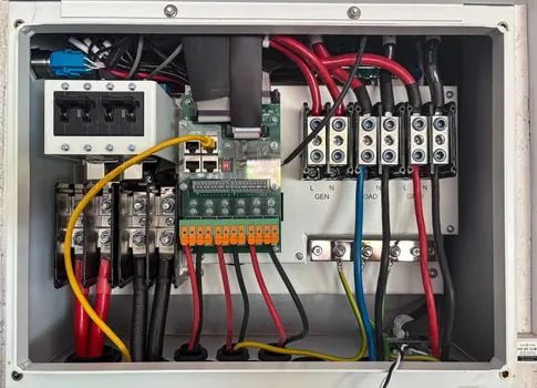
The two checks most often missed on a retrofit are the cable terms: Co of the barrier must cover Ci of the sensor plus Ccable, and Lo must cover Li plus Lcable, with typical instrumentation cable at roughly 100 pF/m and 1 µH/m [S1][S4].
A 500 m run of 2-core shielded cable at ~100 pF/m contributes ~50 nF, which is meaningful against common barrier Co values of a few hundred nF, so long runs force a lower-capacitance cable or an isolator with higher Co on the same entity certificate [S1][S4].
Open-circuit detection, the NAMUR-style off-current of about 1.2 mA (good) versus 2.1 mA (target present), only works when the barrier and sensor are entity-matched for both the live and quiescent states, otherwise the barrier's voltage drop can collapse the sensor below its nominal 8.2 V and force a false "open" reading on the flow sensor loop [S6][S8].
Wiring separation and the 50 mm rule
Intrinsically safe wiring must be physically separated from non-IS wiring in the marshalling cabinet, and IEC 60079-14 calls for a minimum clearance of 50 mm between IS and non-IS terminals, or a grounded metallic partition plate that achieves the same isolation [S1].
This separation requirement applies regardless of whether the barrier is a Zener type or a galvanic isolator, and it is the most common audit finding on brownfield retrofits where a vendor routed non-IS 230 V cable into the same duct as the 2-wire NAMUR proximity loop, voiding the entity parameter match regardless of how clean the math looks on paper [S1].
Common failure modes on a poorly matched loop
Three recurring errors show up on incident logs: using a sensor with Ui below the barrier's Uo so a fault on the safe side drives the sensor above Vmax, ignoring cable capacitance so the loop's total C exceeds barrier Co, and assuming a HART multiplexed loop is entity-compatible with a barrier certified only for analog 4-20 mA [S1][S3].
A fourth pattern, less common but increasing, is pairing an ib-rated proximity switch with an ia-rated barrier in Zone 0; the equipment is individually certified, but the loop is not legal because the sensor is the limiting element on fault count, and a Zone 0 install must use ia on every series element of the IS loop [S4].
Related reading on hazardous-area instrumentation
For the analog signal layer above the barrier, the Ethernet-APL vs 4-20 mA HART comparison walks through how the two protocols split on cable length, intrinsic safety, and segment loading on a typical 2026 transmitter retrofit. [S3]
For plant-wide sensor siting, the toxic gas detection architecture piece covers stack selection, sample-line lag, and where to bring barrier entity-parameter documentation into the engineering design basis.
For control-cabinet layout that respects the 50 mm rule and supports the entity match, the dual power input redundancy writeup covers how redundant power feeds interact with IS-ground integrity on shared DIN-rail systems.
The two control-drawing items an engineer should pull before energizing any IS proximity loop are the barrier's entity certificate (Uo, Io, Po, Co, Lo) and the sensor's entity certificate (Ui, Ii, Pi, Ci, Li); the loop is only IS when all five inequalities pass on those two pages plus the cable C and L totals [S1][S2][S4].