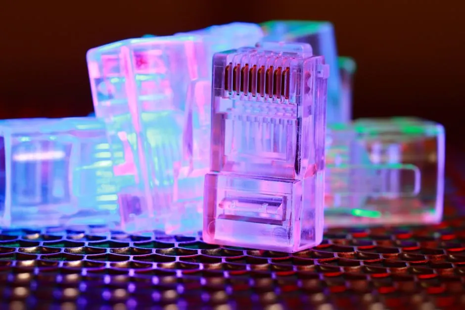
Dual-input redundant power designs on industrial Ethernet switches accept two independent DC sources, typically 24 V on the factory floor or 48-54 V in telecom-grade cabinets, and hand off to the standby feed in under 20 ms when the primary drops out [S3][S5]. The arrangement is sold variously as 1+1 redundancy, dual-power input, or redundant power supply, and is now the baseline expectation for any managed switch specified into substation, oil and gas, transportation, or 24/7 manufacturing networks [S2][S4].
Real-world failure economics drive the spec. A documented auto-plant case traced a 2-hour welding-robot shutdown to a single-power switch failure, with direct losses exceeding 500,000 yuan, the kind of figure that moves the procurement line from a consumer-grade SKU to a dual-input managed part on its own [S5]. This is the architecture behind an industrial switch that has to behave more like a utility asset than an office accessory.
Two Physical Topologies: Dual Inputs vs. Dual Modules
Industrial Ethernet switches implement redundancy in one of two distinct ways, and confusing them on a BOM is the most common sourcing mistake. Topology A is a single internal power module with two external input terminals; both feeds connect simultaneously, internal ORing circuitry monitors both rails, and the switchover is seamless because there is only one converter downstream [S3]. Topology B is full 1+1 redundancy: two independent internal power modules, each fed from a separate source, with either module capable of carrying the full load on its own [S8].
The two topologies differ in serviceability, not in failover speed. A dual-input, single-module switch can be hot-swapped at the supply side but the module itself is field-replaceable only on shutdown. A true 1+1 design supports online module replacement, which is why the high-availability SKU is the right pick for cabinets where opening the panel means a permit-to-work [S8]. Power distribution architecture upstream decides which topology is actually useful: feeding both inputs from the same PDU gives zero real redundancy, a wiring error that defeats the entire feature.
Electrical Specs That Matter: Voltage Range, Failover Time, and Polarity
Wide-range DC input is the rule rather than the exception on industrial-grade parts, with 24 V (9-36 V or 12-48 V window) common for machine-level cabinets and 48-54 V (often 36-75 V) for substation and ITS applications, with reverse-polarity protection on the terminal block as standard [S5][S6]. Failover time of under 20 ms is the published benchmark most vendors quote; the USR-ISG208S-SFP, for example, is documented at sub-20 ms handover with no surveillance frame loss in bench testing [S5].
Beyond raw failover, three secondary specs quietly decide whether the install is actually reliable. First, alarm relay output (a form-C contact that toggles on input loss) for SCADA or BMS integration, which is the only way the loss shows up before a connected device goes silent [S4]. Second, hot-swappable supply modules on the 1+1 topology, so a failed PSU can be replaced without a window [S5][S8]. Third, isolation voltage between the two inputs, typically 1.5 kV, which matters when one feed is grounded and the other is floating. A power supply that does not publish its input-to-input isolation is a sourcing red flag.
Comparison: Single-Power vs. Dual-Power Switch Designs
Side-by-side, the difference is a tradeoff between unit cost and the cost of an unplanned outage. A single-power switch wins on price and simplicity but exposes the entire segment to the failure of one module and one upstream feed, with downtime bounded only by the speed of a manual swap [S5]. A dual-input switch adds an internal ORing stage or a second PSU, plus a second terminal block, and typically costs 30-60% more at the BOM level; the payback math is one avoided production stop [S5].
On the four selection criteria that matter to a process engineer, the comparison lines up as follows. Power availability: single-power is one-fault tolerant only by accident of upstream UPS, dual-input is one-fault tolerant by design [S2][S4]. Maintenance: single-power requires a planned shutdown to replace the module, dual-input 1+1 allows online swap [S5][S8]. Scalability: single-power is bounded by one converter's rating and usually needs full replacement as load grows, dual-input tolerates load creep on the primary while the secondary carries the new draw [S5]. Cost per avoided outage hour: single-power is cheaper until the first incident, after which the math reverses, as the auto-plant case above shows [S5].
Application Fit: Where Dual-Power Is Required vs. Optional
Dual-input power is functionally required in substations, oil and gas facilities, rail signaling, water-treatment SCADA, and any line running a 24/7 continuous process; a single input on these segments is normally rejected at the spec review [S2][S4]. It is also the right call for surveillance and access-control backbones, where a single dropped switch blanks a zone of cameras, and for AGV and robotic-cell rings, where a power-loss-induced STP reconvergence can drop a few hundred milliseconds of motion commands [S5].
It is optional, and often overkill, in non-critical machine-level islands, test benches, and any segment already protected by a downstream device that does not need sub-second failover. A power meter on a non-billable sub-panel does not need 1+1 PSUs. A rule of thumb: if the connected device costs less than the switch, dual-power is wasted.
Integration with Ring, Link, and Device Redundancy
Power redundancy only pays off when paired with the right layer-2 protocols, otherwise a power blip that does not drop the switch still drops the ring. Industrial switches typically combine dual inputs with ERPS (Ethernet Ring Protection Switching, sub-50 ms ring failover) or a proprietary ring protocol, plus MRP or RSTP, and dual uplinks per node so the path also survives a fiber cut [S4][S7]. Device-level redundancy (dual NICs on the PLC or SCADA server) is the third leg, otherwise the surviving switch has no surviving host to talk to.
The wiring mistake that breaks this whole stack is feeding both inputs from the same source. A documented failure mode: both terminals landed on the same 24 VDC PSU, so the redundant-power feature became a zero-redundancy feature and only showed up during a real outage [S4]. Independent feeds, ideally from independent upstream power distribution buses and ideally with separate UPS or battery-backed sources, are the only way the topology actually delivers what it claims. Pairing the right topology with the right cable plant is the other half of the job, and selecting the correct power cable gauge for the run length avoids a separate class of voltage-drop-induced reboots.
Sourcing Checklist and Trackable Signals
For a verifiable procurement spec, demand: two independent DC input terminals, with at least one wide-range window covering 24 V or 48-54 V; reverse-polarity protection; published failover time under 20 ms; form-C alarm relay output; hot-swappable supply modules on 1+1 SKUs; input-to-input isolation voltage; and a published MTBF figure, not a marketing claim [S3][S4][S6]. Confirm the field-replaceable PSU is a separate line item with its own part number, otherwise a failed module becomes a switch replacement. Specifying the wrong adjacent component can quietly defeat the whole design, which is why a stop-category and safety-relay review belongs in the same cabinet-design package, and the same logic applies when sizing inductive sensors on the same 24 V bus so inrush does not collapse the shared rail.
Track two signals through 2026: vendor disclosures of actual failover time measured against EN 50121-4 or IEC 61850-3 environments, and any shift in 24 V vs. 48 V default input windows on new managed switch releases; both are leading indicators of where the substation and ITS market is moving on the dual-power baseline.