Industrial expansion joints are specified to absorb thermal growth, isolate vibration, and compensate for minor misalignment, yet most premature failures trace back to installation errors rather than bad design data [S1][S4]. Correct install follows a six-step workflow: joint selection, vibration isolation, guide and anchor layout, pre-install prep, precision bolting, and recurring inspection [S1].
The most common field failures, including over-extension, braid wear, lateral offset, and flange distortion, all map back to torsion during fit-up, missing pipe guides, or torque applied unevenly [S1][S2]. For pump-suction and turbine-exhaust services, the same hardware but a different control-rod setup applies, and expansion joint selection must match both movement envelope and pressure thrust before a flange is ever mated.
Step 1: Joint Selection Against Media, Temperature, and Pressure
Selection runs on a 5-point match: media compatibility, design temperature, design pressure, movement envelope (axial, lateral, angular), and end-connection style, with the wrong joint introducing stresses that produce leaks or early fatigue [S1]. For process piping in chemical and refinery service, ASME B31.3 Process Piping is the governing reference for material, design, and fabrication [S1].
Elastomeric and PTFE-body joints suit low-pressure water, slurry, and chemical service; metal bellows joints are specified where temperatures exceed the elastomer ceiling or where cyclic life targets run into the thousands of cycles [S1][S3]. Garlock's elastomer-joint manual covers control units, misalignment measurement, and installation steps for non-metallic styles, while Precision Hose's metal-bellows instructions warn that thin-gauge convolutions lose cycle life and pressure capacity if mishandled [S3][S5].
Step 2: Pump Connectors and Vibration Isolation
Pump vibration is as damaging as thermal growth in many systems, and pump connectors isolate that vibration, absorb minor misalignment, and protect mechanical seals and bearings [S1]. Selection between metal and rubber pump connectors depends on temperature, chemical compatibility, and the magnitude of the vibration source.
When a piping run includes a centrifugal pump, compressor, or turbine, the rule of thumb is to place the connector close to the equipment nozzle and pair it with the expansion anchor layout so thrust loads are absorbed upstream of the connector. The joint itself does not restrain pressure thrust; anchors do that job [S1][S4].
Step 3: Pipe Guides, Anchors, and the 4-10 Diameter Rule

Expansion joints absorb movement but do not control its direction, so pipe guides and anchors must be set before the joint is installed [S1]. The first pipe guide is typically placed 4-10 pipe diameters from the joint, with additional guides at charted intervals based on diameter, layout, and service [S1].
Anchors absorb pressure thrust, and the combined guide-anchor system keeps the joint operating inside its stated movement envelope [S1]. Mercer Rubber's bolted-joint procedure requires a numbered cross-pattern bolt sequence so flange faces load evenly, a method that pairs naturally with the guide-spacing chart when laying out long runs [S2].
Step 4: Pre-Install Preparation, Storage, and Transport Fittings
Belman's September 2026 guidance states that a joint must be lifted only at the end fittings, never by slings or chains around the bellows, and must be stored on a flat surface under cover [S4]. Transport and pre-tensioning bars, identified by yellow-and-black striped tape, must stay in place until installation, since removing them early lets the joint move into an incorrect condition that endangers workers and shortens service life [S4].
Before fit-up, verify the joint is free of dents, damaged fittings, incipient rust, insulation debris, and that the pipeline gap matches the specified installation length within design tolerance [S4]. Clean the flange sealing surfaces, align the piping so the joint is not forced into compression, extension, or lateral offset at install, and mark the neutral length at mean operating temperature so the joint can travel both ways once in service [S1][S4].
Step 5: Install with No Torsion, Even Torque, Control Rods Where Needed
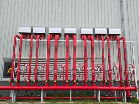
Field installation rules are concrete: never twist the joint to align bolt holes, rotate the flange or re-align the pipe instead; set the joint at neutral length; tighten bolts in a star or cross pattern to avoid flange distortion; and install control or limit rods where thrust loads are uncertain [S1][S2]. Mercer Rubber's procedure numbers the bolts in a cross-pattern sequence to keep gasket compression uniform across the face [S2].
For metal bellows, Precision Hose adds that the piping system must fit the joint, not the other way around, and that single Van Stone liners must point in the direction of flow [S3]. Proco's installation instructions reiterate the same fit-up logic for elastomeric and PTFE-body joints, reinforcing the no-torsion, no-offset, neutral-length rule across both metal and non-metallic product lines [S6].
Step 6: Inspection, Maintenance, and the Annual Cycle
Annual visual inspection is the minimum, with checks for over-extension, lateral misalignment, braid wear, and loss of flexibility, and immediate replacement where any of those conditions appear [S1]. Re-torque after the first thermal cycle is standard because gasket seating relaxes once the system goes from ambient to operating temperature [S1].
Documentation closes the loop: record torque values, neutral length, guide locations, and any field adjustments so the next outage has a baseline [S1]. For facilities that route compressed air or process gas through the same pipe rack, the same torque-and-guide logic applies, and pairing this procedure with a compressed air line design walkthrough reduces mixed-service call-backs during commissioning.
Comparison: Elastomeric vs Metal Bellows vs Fabric Joints at Install
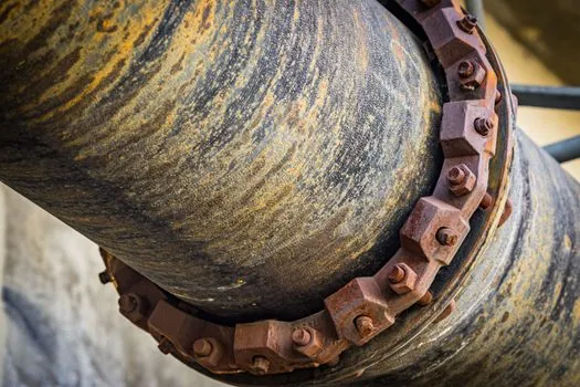
Across the three main families, install trade-offs are sharp. Elastomeric joints (EPDM, Neoprene, Viton, PTFE-lined) ship lighter, tolerate more misalignment at the flange face, and need only even bolt torque, but cap out at moderate temperatures and pressures. Metal bellows joints carry higher temperatures and pressures and offer defined cycle life, yet require strict guide spacing, controlled torque, and a no-lift-on-bellows handling rule [S3][S4]. Fabric and ducting joints are the lightest, suit low-pressure flue and ventilation service, and install with the same no-torsion logic, but rely on the surrounding duct structure for thrust restraint rather than piping anchors [S5].
When to Repair vs When to Replace and What to Escalate
Repair is acceptable for a single thermal-cycle re-torque, a re-marked neutral length, or a re-aligned guide, but not for visible braid fray, bellows denting, permanent set after a pressure excursion, or any case where the joint has moved outside its design envelope [S1][S4]. Belman's 2026 manual flags that failure to follow storage, handling, and install rules can reduce both service life and pressure capacity, and recommends replacement over field repair when the unit has been subjected to torsion or impact during handling [S4].
Escalate when the calculated thermal expansion exceeds the joint's stated movement, when anchors are missing or undersized, or when the service has shifted from the original design basis (new chemical, higher temperature, more cycles). For plants running parallel systems like a packaged compressor skid, cross-check the packaging machinery market share vendor map only as a sourcing signal, not a substitute for verifying the joint's own design data.
Track two signals into the next outage: re-torque values after the first full thermal cycle, and any change in guide spacing during the annual walk-down. If either drifts from the install record, schedule a joint replacement during the next planned turnaround rather than waiting for a leak.
Spec-level background on the components involved: linear guide.