
A well-engineered compressed air production line recovers 20-50% of lifecycle energy cost through right-sizing, with every 2 PSI of unnecessary discharge pressure adding roughly 1.6-2% to compressor power consumption [S1][S4].
The design envelope is governed by three independent variables: airflow in CFM, discharge pressure in PSI, and ISO 8573-1 air quality class, with the compressor rated at a specific CFM at a specific pressure (e.g., 100 CFM at 100 PSI) [S1]. Lifecycle cost is dominated by energy (a compressor converts roughly 90% of input electricity into heat, of which up to 90% is recoverable) rather than capital, so pipe sizing, pressure drop, and receiver placement are the highest-leverage design decisions [S4][S5].
Sizing the Compressor to Real CFM Demand
Peak CFM, not nameplate HP, is the correct sizing basis, with operating pressure and duty cycle collected per downstream tool before selecting the machine [S1][S3]. A pump-up test or in-line flow meter on an existing receiver validates the calculated figure, and leak plus friction losses (often 10-30% of generated volume in unmaintained plants) must be added back into the capacity budget [S1]. Oversizing by more than ~10% above measured peak CFM pushes the unit into inefficient part-load; undersizing triggers pressure decay and downstream tool starvation [S3].
Compressor Type Selection Across the Pressure Map
Rotary screw compressors dominate the 50-250 PSI continuous-duty range used in most discrete and process manufacturing, while oil-free screw or centrifugal units are mandatory for ISO 8573-1 Class 0-2 (pharmaceutical, electronics, breathing air) [S1][S5]. Piston compressors remain common in small workshops and intermittent-duty vehicle service shops below ~50 CFM, and centrifugal units are the economic choice above roughly 1,000 CFM where heat recovery and turndown justify the package [S5]. The cost-of-ownership crossover between oil-injected and oil-free is typically 15-25% higher first cost for oil-free, recouped when contamination rejection eliminates post-filtration or product scrap [S4].
Air Treatment Stack by ISO 8573-1 Class
ISO 8573-1 grades compressed air purity on three axes (particulate [A], moisture [B], oil [C]) on a 0-10 inverted scale, and the treatment train is selected directly from the worst-case axis of the end use [S1]. Class 5-6 suits tire fill, general shop air, and sandblasting; Class 3-4 covers spray painting, automotive assembly, packaging, and plastics/blow molding (the latter is the natural anchor for downstream molding line integration); Class 0-2 is required for pharmaceutical, food and beverage, semiconductor, and medical or breathing-air service [S1]. The standard equipment train is a particulate pre-filter at the compressor outlet, a refrigerant or desiccant dryer, a coalescing filter for oil aerosol, and an activated-carbon stage when total oil carryover must drop below 0.003 mg/m³ [S1][S4][S5].
Distribution Piping, Pressure Drop, and Receiver Sizing
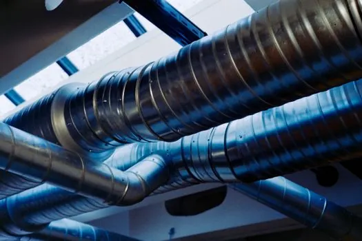
Ring-main aluminium or stainless piping is preferred over dead-end branches because it equalises pressure and limits peak velocity below roughly 6 m/s, which keeps frictional pressure drop under 0.1 bar per 100 m at design flow [S4][S6]. The CAGI rule that every 2 PSI (0.14 bar) of additional discharge pressure raises compressor energy use by 1.6-2% means the piping design directly governs kWh cost, so loop diameter should be selected for a target pressure-delta of no more than 0.3-0.5 bar end-to-end [S4]. A receiver sized at roughly 1 gallon per CFM of compressor capacity (or per ISO 1217 FAD x 4-6 seconds of peak demand) damps pulsation, buffers peak demand, and is built to AS 1210 with state-by-state pressure-vessel registration [S5]. Air filters and lubricators should mount within 5 µm of the branch take-off, and the compressor should be mechanically isolated from the distribution network to keep vibration out of the header [S6].
Controls, Heat Recovery, and Condensate Management
Variable-speed drive (VSD) screw compressors save 25-35% of part-load energy when demand varies more than ~30% of nameplate, and they are now standard on rotary-screw packages above 30 kW [S2][S4]. Approximately 90% of the input electrical energy leaves the compressor as recoverable heat, typically 60-80°C at the oil cooler, which can be ducted to space heat, paint-booth pre-heat, or process water via a plate heat exchanger [S4][S5]. Condensate from the after-cooler and dryer carries compressor oil and must pass through an oil-water separator (typically achieving below 10 mg/L total oil) before drain, with the separator sized for the design dew point and ambient temperature [S4][S5]. For plants building automatic molding line cells, the control stack commonly extends to a air solenoid valve manifold per station, with feedback from an air quality monitor on the Class 1-2 branch to interlock the line on contamination events.
Common Failure Modes and Specification Traps
Undersized receivers produce a saw-tooth pressure profile that confuses pressure-switch controls and accelerates compressor cycling, cutting bearing and contactor life in half on reciprocating units [S1][S3]. Dryer undersizing is the most common cause of moisture carryover in plants that otherwise meet ISO 8573-1 Class 4, with refrigerated dryers needing a 5°C margin below the required pressure-dew point and desiccant dryers needing 20-30% extra adsorption capacity for elevated inlet temperature [S4][S5]. Galvanic corrosion at aluminium-to-steel transition fittings is a recurring leak source; dielectric unions or full-aluminium ring-mains with stainless drops eliminate the bimetallic couple [S4][S6]. For end-uses such as air impact wrench or air pick stations in vehicle service, the final regulator should be sized for 1.5-2x tool CFM to prevent regulator freeze and pressure sag under stall [S3][S7].
For projects commissioning new capacity, two trackable signals confirm a clean design: a documented ISO 8573-1 [A][B][C] class on every P&ID branch, and a measured pressure-delta at full load under 0.5 bar end-to-end across the ring main, both of which can be tied to the as-built log for warranty validation [S4][S5].
See also our earlier report, Power Mixer Safety: Lockout, Vibration, and ATEX Gates.