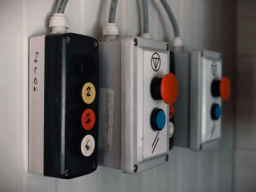
A correctly specified explosion-proof control station reconciles six items at once: hazardous area classification, control functions and logic, certification scheme, enclosure material, ingress protection, and installation conditions [S1].
Pump stations, loading racks, tank farms, and chemical skids all depend on a local station that puts start, stop, and emergency-stop within arm's reach of an operator standing in a classified area, with HLBX02 and HLBX03 series units marked Ex II 2G Ex db eb IIC T6 Gb for gas and Ex II 2D Ex tb IIIC T80 °C Db for dust under IEC 60079-0, -1, -7, and -31 [S1].
Step 1: Lock the Hazardous Area Classification Before Anything Else
Area classification must be resolved before any model is selected, because Zone 1, Zone 2, Zone 21, Zone 22, Class I Division 1, and Class I Division 2 are not interchangeable schemes and must be confirmed separately [S1][S3]. Gas group IIA, IIB, or IIC and temperature class T1 to T6 are also determined by the process media at the location, and a station rated T6 at +40 °C may carry a different rating at +60 °C because the surface temperature limit interacts with ambient [S1]. Pump skids and tanker loading points frequently fall in Zone 1, while surrounding areas are often Zone 2, and sulphur handling, coking, and mixed process areas add dust zones (Zone 21/22) on top of the gas zone [S1].
For North American projects the same station may need both UL 1203 (explosion-proof and dust-ignition-proof equipment) and the NEC Class/Division scheme, while European and most international projects use ATEX 2014/34/EU and IECEx, and these certifications are not drop-in equivalents [S2][S3]. Product naming alone ("explosion-proof") tells you nothing about which zone, gas group, or T-code the station is actually certified for, so the area classification drawing, the gas group, and the T-code all have to be on the spec sheet before the enclosure is chosen [S1].
Step 2: Build the Operator List, Then Size the Enclosure
Enclosure size follows from the operator count, but not on a one-button-one-hole basis: typical pump-station layouts run Start, Stop, Emergency Stop, Local/Remote, Manual/Auto, running indication, and fault indication, while loading-rack layouts swap in Pump Start/Stop, Valve Open/Close, loading status, and alarm indication [S1]. Push-buttons, selector switches, emergency-stop switches, pilot lights, combination control devices, and control circuit interfaces are the six device families that fill the front plate, and the layout has to follow the control logic of the equipment, not the other way round [S1][S2].
Enclosure size is then driven by three things: the operator footprint on the front plate, the internal termination space behind each device, and spare capacity for future expansion [S1][S3]. An under-sized enclosure forces devices too close together, violates creepage and clearance, and leaves no room to land conductors, so a 20 to 30 percent spare footprint and spare terminal block rows is a practical minimum, not a luxury [S3]. For pendant stations the layout is different: the device is handheld, the enclosure is smaller, and the design focus shifts to impact resistance, grip ergonomics, and strain relief on the cable entry rather than a multi-operator faceplate [S4].
Step 3: Match Enclosure Material, Ingress, and Operator Type to the Environment

Cast aluminum and stainless steel are the two dominant enclosure materials, with glass-reinforced polyester (GRP) used where impact and corrosion resistance are both critical [S3][S4]. Aluminum cuts weight and cost on offshore modules and skid packages, while 316L stainless is the default for coastal, chemical, and pharmaceutical sites where chloride attack is a concern, and GRP shows up in wastewater and mining where rough handling and corrosion combine [S3][S4]. Ingress protection typically lands at IP65 or IP66, with NEMA 4X as the NEC equivalent for wash-down and outdoor exposure, and NEMA 7 reserved for Class I Division 1 areas where the enclosure must contain an internal explosion [S3][S5].
Material choice cascades into component choice: aluminum enclosures pair naturally with explosion-proof buttons rated for the same ambient range, and any pilot light, ammeter, or explosion-proof distribution internals mounted inside the station have to be certified to the same T-code and gas group as the enclosure itself, otherwise the assembly is no longer covered by the station's certificate [S1][S3].
Step 4: Confirm Certification, Cable Entry, and Sealing Method
Certification schemes to look for in parallel: UL 1203 and UL 844 for North American hazardous locations, ATEX 2014/34/EU for the EU, and IECEx for international projects, plus UL 924 if the station also carries egress or emergency-stop lighting functions [S2][S3][S5]. OSHA, NEC, and CEC govern the installation side, and the station's label has to show every marking that the inspector will look for, including the Ex string, the gas group, the T-code, and the ambient temperature range [S2][S3].
Cable entry is the most common inspection failure point: threaded hubs and conduit openings have to match the certified entries on the enclosure, and unused entries must be closed with certified blanking elements, not off-the-shelf plugs [S3]. Flamepath joints, threaded covers, and conduit interfaces are the engineered clearances that cool any escaping hot gas below the auto-ignition temperature of the surrounding atmosphere, and they only work if they are assembled to the manufacturer's torque and gap specification, with approved sealing fittings installed per NEC 500 to 516 [S2][S5]. For pendant stations, additional attention goes to the cable gland and the strain relief at the handheld end, because pendant cables see continuous flexing in service [S4].
Step 5: Compare Main Configurations Against Decision Criteria
Three configurations cover the majority of projects, and the choice between them is driven by zone, ambient, and operator count rather than by brand: [S1]
Wall-mounted multi-operator stations (HEXLON HLBX02 / HLBX03 pattern) suit Zone 1/21 with up to 6 to 8 operators, Ex db eb IIC T6 Gb, ambient typically -20 to +60 °C, aluminum or stainless enclosure, IP66, IEC 60079 series compliant [S1].
Pendant stations (Wilmall Ex d pendant pattern) suit Zone 1/21 with 2 to 6 buttons, ATEX and IECEx certified, GRP or aluminum body, designed for crane, hoist, and machinery remote control where the operator moves with the load [S4].
Combination control stations (control box plus pilot light and ammeter) suit Class I Division 1 and Zone 1 with mixed operator and indicator functions, often paired with a explosion-proof motor starter in the same skid, larger enclosure footprint, UL 1203 or ATEX-certified, IP66 or NEMA 4X [S2][S3].
Decision rule: pick wall-mounted multi-operator for fixed pump skids and loading racks, pick pendant for crane and hoist duty, pick combination box when a motor starter, explosion-proof junction box termination, or pilot instrumentation is integrated in the same enclosure, and avoid GRP pendants in heavy-impact zones where the housing can crack and break the flamepath [S1][S3][S4].
Common Failure Modes and What to Avoid
The four most common ways a control station project goes wrong: (1) ordering a Zone 2 station for a Zone 1 location, which fails inspection on day one; (2) choosing a T6-rated station for a process whose auto-ignition requires T4 or T5 and over-specifying surface temperature, which inflates cost without safety benefit; (3) using non-certified cable glands or leaving unused entries open, which breaks the flamepath integrity of the entire enclosure; (4) ignoring ambient temperature, where a station rated for +40 °C is installed in a +55 °C shelter and the T-code no longer holds [S1][S3][S5].
For project engineers working across both schemes, a common trap is treating Class I Division 1 and Zone 1 as identical, and Zone 2 as identical to Class I Division 2: they are similar in concept but certified separately, and equipment rated to only one scheme is not automatically acceptable under the other without an equivalent certification or a documented variance [S1][S3].
Trackable Signals and Related Reading
Two signals worth watching in the next sourcing cycle: (a) whether the IEC 60079-0 and -1 series continues to be cited as the reference flamepath standard on new EU and IECEx certificates, and (b) whether more vendors are publishing combined C1D1 and Zone 1 dual-marked stations, which removes the cross-certification step for projects specified to both schemes [S1][S2][S3].
For sizing the wiring side of the same skid, pair this guide with a walkthrough on control cable selection and shielding for hazardous-area stations so the cable spec stays consistent with the enclosure's T-code and gas group.