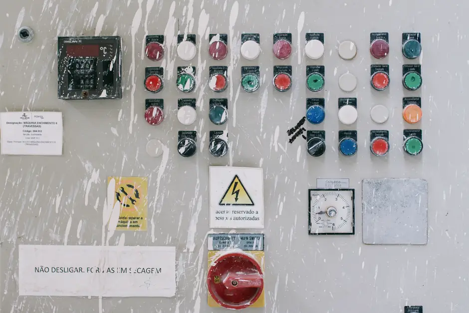
A fail-safe motor protection relay trip output is energized during healthy operation and de-energizes to trip the breaker on fault, on loss of relay power, or on internal self-test failure (HALARM), per SEL application note AN2013-18 [S2].
Nonfail-safe (the default on SEL-849 OUT01-OUT03) holds the trip contact open in the healthy state and only closes it when the trip logic asserts, leaving the motor unprotected during any control-power interruption, per SEL application note AN2021-01 [S3].
Definitions and Contact States
SEL defines fail-safe as "an output contact that is energized during normal relay operation and is de-energized when relay power is removed or if the relay fails," with the relay coil continuously energized while the unit is powered and operational, and the normally-closed contact held open by that coil until a trip occurs [S3].
The contact-state table for SEL-849 OUT01 shows fail-safe = E1-E2 closed, E1-E3 open when powered and healthy, then both contacts reverting to their de-energized positions (E1-E2 open, E1-E3 closed) on power loss or self-test fail, which is the action that drops the breaker [S3]. Rockwell Automation's 825-P trip relay uses the same convention: 95/96 opens and 95/98 closes when the coil drops out, and "most applications" select fail-safe "as at the absence of control voltage the trip relay contact 95/96 opens, therewith the motor is stopped and herewith protected" [S4].
Selection Criteria: When Fail-Safe Is the Right Choice
Choose fail-safe (normally-energized) trip when backup protection is too slow to prevent equipment damage, when a failed feeder relay must trip locally to avoid a main-bus trip, or when the arc-flash hazard rating downstream assumes the breaker will open on relay failure, per the explicit selection logic in AN2013-18 [S2].
Choose nonfail-safe when the driven process must keep running through a relay power interruption, accepting that the motor is unprotected during the outage, which is the situation Rockwell flags as "a running motor is not protected during the absence time of the control voltage" [S4]. Typical pump, fan, and compressor loads in continuous-process plants fall into this category only after a documented risk decision, not by default.
Criteria Comparison of the Two Wiring Modes

The four decision criteria below are the ones process engineers actually argue about in a kickoff meeting, and they line up directly with the source documentation: [S5]
1. Behavior on loss of relay/control power. Fail-safe trips the breaker (motor stops, equipment protected); nonfail-safe leaves the breaker closed (motor keeps running, unprotected) [S3][S4].
2. Behavior on internal relay self-test failure. Fail-safe de-energizes the trip output and asserts HALARM, opening the breaker, while disabling all other protection until the unit is replaced [S2]. Nonfail-safe does the same on a self-test fail only if the contact has been configured fail-safe; otherwise the motor is unprotected while the relay restarts itself several times attempting to clear the fault [S2][S3].
3. Healthy-state contact position. Fail-safe: trip coil of the output contact is energized and the NC contact is mechanically held open [S3]. Nonfail-safe: trip coil is de-energized and the NO contact is at rest open until the trip logic asserts [S4].
4. Suitability for motor loads with high restart cost (large motors, high-inertia fans, refining column pumps). Fail-safe is preferred because the cost of an unprotected run-down under fault is higher than the cost of a controlled trip, a position consistent with IEEE PSRC guidance on local breaker failure initiation from any relay that trips the breaker [S5]. Nonfail-safe is acceptable only where a controlled coast-down is itself a process hazard, e.g. a pump that must keep circulating coolant through an exothermic reactor during a brief power dip.
Wiring the Trip Path
For SEL-700 series feeder/motor relays, the implementation is to add the trip bit into the output equation for a normally-closed b contact, set the fail-safe setting for that trip output to Y, and wire the normally-closed contact between pins 07 and 09 of Output 103 (Form C), as documented in AN2013-18 [S2].
For the SEL-849, the procedure is to change FACTLOG from Y to N so that OUT01 becomes visible, then set the OUT01 fail-safe bit to Y under Settings > Protection > Output Settings, and wire the trip output through the E1-E2 contact so that loss of coil current drops the breaker [S3]. For the Allen-Bradley 825-P, the equivalent parameter lives at SET/SHOW, RELAY, RELAY BEHAVIOR, and the terminal labels for 95/96 and 95/98 swap depending on which mode is selected, so the wiring diagram has to be re-read after any mode change [S4]. For background on how the trip coil fits into a protective relaying system alongside the 52 breaker contact, CTs/VTs, and the DC station battery, see the motor protection relay reference page.
DC Trip Circuit and Breaker-Failure Considerations
The IEEE Power System Relaying Committee's Relay Trip Circuit Design guide notes that "breaker failure relaying is usually initiated by all protective relays which trip the breaker," which means a fail-safe trip path and the breaker-failure initiator should be designed together so that a single failed trip contact cannot silently disable both functions [S5].
Test-Guy's protective relay test notes define breaker failure relaying as "the use of a current monitoring relay to determine whether or not current continues to flow into a faulted circuit," which is the backstop that catches the case where a fail-safe output commanded the breaker open but the 52 mechanism did not actually interrupt current [S6]. On continuously-energized trip coils, IEEE PSRC further recommends separating relay logic circuits from breaker trip circuits and supervising the DC supply, because a break in the trip wiring or a blown fuse in a normally-energized coil loop will itself look like a trip command, which is a feature for safety but a maintenance liability that has to be designed out via trip circuit monitoring [S5]. For a broader framing of where the motor protection relay sits inside the protection chain, see the protection relay overview and the microcomputer protection page covering how digital self-test interacts with the fail-safe output.
Failure Modes and Maintenance Traps
The two failure modes that bite fail-safe installations are: (a) an open break in the trip wiring or a blown fuse in the coil feed, which drops the breaker under no-fault conditions, and (b) a failed relay that latches HALARM and de-energizes every output until the unit is replaced, which is the intended safety outcome but stops the process, so the spare-relay MTTR effectively defines the process downtime [S2][S3].
The two traps specific to nonfail-safe installations are: (a) loss of control voltage, which Rockwell explicitly states leaves "a running motor ... not protected during the absence time of the control voltage," and (b) misreading the terminal labels after switching a 825-P from nonfail-safe to fail-safe, because the 95/96 and 95/98 designations swap, and the wiring diagram from the previous mode will now drive the wrong contact [S4]. For interposing auxiliary relays between a low-energy digital trip output and a high-current breaker trip coil, the selection criteria around coil burden, dropout voltage, and Form C contact wiring are covered in the industrial relay and relay module reference pages.
Trackable signals for the next planning cycle: IEC 60255 trip-output electrical durability tests (mechanical and electrical endurance ratings on Form C contacts) and any OEM revision to the default fail-safe bit on the SEL-849 OUT01-03 outputs, which today ship as nonfail-safe per factory logic and require a deliberate FACTLOG change to enable fail-safe on OUT01 [S3].
For related coverage, see Single-Acting vs Double-Acting Plunger Pump: Selection Matrix.