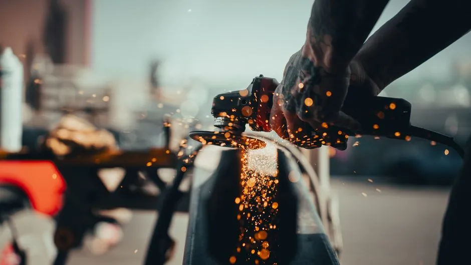
Select fettling grinder power from the wheel width and required removal rate, then match the wheel diameter to the machine speed and control requirement.
For a 2×72-inch belt grinder with a 3,450 RPM motor and 1:1 direct drive, drive wheels from 3 to 8 inches produce about 2,710 to 7,230 surface feet per minute (SFPM), making drive-wheel diameter a speed-control variable as well as a power consideration [S1].
Power and wheel width define the work class
A useful starting point for fettling-grinder motor sizing is 15 to 20 HP per inch of wheel width, with high horsepower supporting harder abrasive grades and lower horsepower favoring softer grades [S3]. This is a ballpark design rule, not a substitute for checking stock removal rate, duty cycle, starting current, and machine construction.
Motor power is useful only when the abrasive retains speed under load. A motor that reaches its free-running RPM but slows during contact gives the wheel less effective cutting energy. Higher-amperage tools sustain speed more effectively under pressure, while a lower-power tool can bog down when the operator uses an aggressive grinding angle [S2].
The wheel’s width determines how many cutting grains can engage the workpiece at one time, so a wider wheel is not simply a scaled version of a narrow wheel. The article gives a ballpark motor-sizing figure of 15–20 HP per inch of wheel width, but it does not specify how that figure applies to a 2×72 belt grinder [S3].
Wheel diameter changes speed and handling
On a 2×72-inch belt grinder, belt speed can be calculated as drive-wheel diameter in inches × 0.262 × shaft RPM [S1]. At 3,450 RPM with 1:1 direct drive, a 3-inch drive wheel gives about 2,710 SFPM, a 5-inch wheel about 4,520 SFPM, and an 8-inch wheel about 7,230 SFPM [S1].
At 3450 RPM with 1:1 direct drive, the chart lists about 3,610 SFPM for a 4-inch drive wheel, about 4,520 SFPM for a 5-inch wheel, and about 5,420 SFPM for a 6-inch wheel; smaller drive wheels generally provide better control but may limit stock removal when motor power and RPM are already limited [S1]. An 8-inch wheel maximizes belt speed in that comparison, but the increase is useful only when belt quality, tracking stability, motor capability, and operator control can support it [S1].
A variable-frequency drive can reduce or increase belt speed in direct proportion to motor speed. It therefore complements mechanical diameter selection: the wheel establishes the available range, and the drive permits fine adjustment within it [S1].
Compare motor and wheel combinations
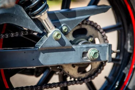
For finish blending, tool shaping, and controlled detail work, a smaller 4-inch wheel at about 3,610 SFPM is easier to modulate, provided the motor does not become overloaded during prolonged passes [S1].
For maximum production speed, an 8-inch drive wheel reaches about 7,230 SFPM at 3,450 RPM, but it transfers the greatest demand to the belt, tracking system, power transmission, and operator [S1]. It should not be selected solely from the diameter chart or by adding horsepower without checking the complete drive system [S1].
Portable grinding wheels create a different selection rule: their marked RPM must equal or exceed the tool RPM, and larger wheels generally belong on lower-RPM tools while smaller wheels suit higher-RPM tools [S2]. A 6-inch wheel should not be substituted for an approved smaller wheel on a high-speed grinder without verifying the tool, guard, and wheel rating.
Match the abrasive to the power and speed
For a fixed abrasive, wheel diameter determines peripheral speed: at the same 2,900 RPM, an 8-inch bench-grinder wheel travels 608.7 ft/min, compared with 382.3 ft/min for a 6-inch wheel and 254.5 ft/min for a 4-inch wheel [S4]. These calculated values show why a smaller wheel cannot deliver the same surface speed as a larger wheel at the same motor RPM.
Power also changes abrasive behavior. This is a process-response comparison, not a universal ranking of abrasive life.
Diameter and thickness both influence wheel usability, while bond, grain, and fiberglass reinforcement determine how the wheel supports the work [S5].
Set power for duty, safety, and machine limits
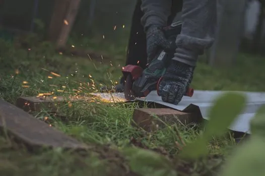
The abrasive must never be operated above its marked speed. Over-speeding creates a significant safety hazard, and an abrasive used at the wrong speed can reduce productivity while damaging the workpiece or wheel [S2]. The arbor bore must match the spindle precisely, the wheel must seat correctly, and the guard must remain in place during operation [S2].
For bench-grinder applications, Australian guidance identifies 150 mm (6-inch) wheels for hobby and light workshop use, 200 mm (8-inch) wheels as a workshop standard, 250 mm (10-inch) wheels for production, and 300 mm (12-inch) or larger wheels for industrial heavy duty [S4]. Pedestal grinders commonly use 8–14 inch wheels, while bench grinders typically use 6–8 inch wheels [S6].
Apply the selection sequence on the shop floor
Start with the production requirement, then apply the 15–20 HP per inch of wheel-width rule as an initial screen for the fettling grinder [S3]. Next, calculate the abrasive speed from actual wheel diameter and RPM, including any reducer, belt ratio, or VFD frequency limit [S1]. Select the abrasive grade and grain to match the material and available power rather than correcting a low-power machine solely by changing abrasive [S2][S3].
Verify compatibility with the machine and abrasive before operation: RPM rating, bore diameter, work-rest clearance, guard, and side-grinding prohibition must all be satisfied [S2][S4]. For a first installation, record full-load current, abrasive speed, belt tracking, stock-removal rate, and surface temperature at the intended work mix. A change in drive-wheel diameter, abrasive grade, feed pressure, or material class should trigger a repeat of those checks.