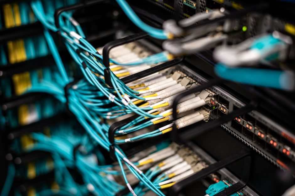
Fiber optic sensors and inductive proximity sensors answer overlapping but fundamentally different questions: one reads light returning through a fiber bundle, the other reads eddy-current damping on a metallic target. Picking the wrong one costs weeks of integration time and a stack of mismatched stock.
This 2026-07-24 reference lines the two technologies against detection distance, target material, environment, and lifecycle, so process and controls engineers can match a sensor to a real plant decision rather than to a catalog page.
Operating Principle and Sensing Mechanism
A fiber optic sensor separates the optoelectronic amplifier from the actual sensing point: the amplifier drives light through a thin glass or plastic fiber, and the fiber tip either emits/receives (through-beam) or senses returned light from a reflective target (diffuse-reflective) [S2][S3]. Because the fiber itself is passive glass or polymer, the active electronics can sit metres away in a safe cabinet while only the flexible fiber enters the process [S2].
An inductive sensor is the opposite topology: a single sealed block contains an LC oscillator, a coil wound around a ferrite core, and a detector. When a metal target enters the electromagnetic field, eddy-current losses shift the oscillator amplitude or frequency, and the detector trips an NPN/PNP or IO-Link output. The sensing face is the face of the housing, and everything — coil, oscillator, output stage — is potted inside an IP67-rated block [S2].
Detection Range, Target Material, and Resolution
Fiber optic amplifiers are typically specified with a sensing range of a few millimetres to roughly 20 mm for diffuse-reflective fibers, and tens of millimetres to a few hundred millimetres for through-beam fibers, with sub-millimetre resolution on small parts — the spot size is set by the fiber core diameter, commonly 0.1–1.5 mm for plastic fibers [S2][S4]. Manufacturers like Baumer publish portfolios exceeding 350 customised fiber-optic variants targeting exactly this kind of micro-detection job [S5].
Standard tubular inductive sensors in the common M8/M12/M18/M30 form factors are specified in the 1–15 mm nominal sensing range band (e.g. an M12 flush-mount typically lands at 2–4 mm nominal Sn), with switching frequencies from roughly 500 Hz for M30 up to 5 kHz and above for small-diameter M5/M8 units [S2]. Inductive sensing is strictly limited to conductive (mainly ferrous and non-ferrous metal) targets; fiber optic sensing reads colour, transparency, contrast, and surface reflectivity on paper, plastic, glass, liquid, and biological samples [S1][S3].
Environmental Limits: Temperature, Chemicals, Hazardous Areas
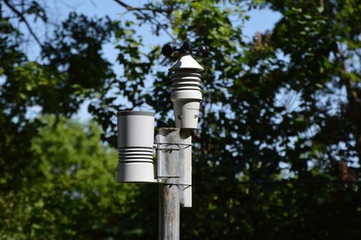
Plastic fiber tips are generally rated from roughly −40 °C to +70 °C continuous, with special polymer or glass fibers extending the upper end past 200 °C, and the remote amplifier can be derated or relocated into a cooler enclosure [S2][S4]. Because the fiber is intrinsically a passive dielectric and carries no current into the sensing zone, fiber optic sensors are a natural fit for explosive atmospheres — the intrinsically safe classification is a defining benefit in paint booths, solvent rooms, and chemical skids [S1][S2].
Inductive sensors carry an operating temperature window that commonly spans −25 °C to +70 °C for industrial-grade potted units, with extended −40 °C to +85 °C variants available, and IP67/IP69K ingress ratings are standard on most M-series bodies [S2]. They are inherently non-contact and immune to dust, oil, and coolant films on the sensing face, which is why they are the default for CNC tool setters and stamping-press end-of-stroke confirmations. A typical drawback worth flagging: inductive sensors are not rated for direct high-temperature or strong-acid submersion the way a remote-mounted fiber tip can be.
Decision Matrix: Four Criteria, Two Technologies
Use this 4-criterion comparison to shortlist the technology before you open a catalog: (1) Target material — metal only → inductive; anything else, including transparent, glossy, or biological, → fiber optic [S1][S3]. (2) Sensing distance — below 20 mm on a small part → either, but fiber wins on sub-mm targets; above 50 mm and on a metal target → inductive or through-beam fiber [S2][S5]. (3) Environment — hazardous area, high temperature, or aggressive wash-down at the sensing point → fiber optic with remote amplifier; oily/dusty but otherwise benign shop floor with a metal target → inductive [S1][S2]. (4) Output integration — IO-Link diagnostics, M12 connector, no optical alignment → inductive; analog or digital threshold on returned light, fine gain teach-in, multi-mode amplifier → fiber optic [S2][S4].
The matrix collapses neatly: if the target is metal and the cycle is fast, inductive is the correct first call. If the target is non-metallic, small, transparent, or the sensing point is hot/explosive, fiber optic is the correct first call. The gray zone — small metal targets in tight tooling — usually goes to a shielded M5 or M8 inductive for cost, unless the surrounding temperature forces a fiber-optic rethink.
Integration Footprint, Wiring, and Lifetime
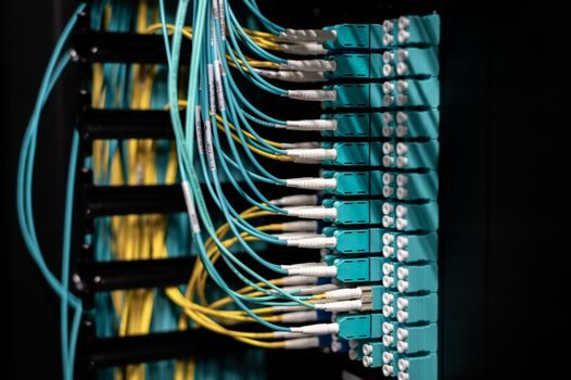
Fiber optic systems are two-piece: a remote amplifier (DIN-rail or panel-mount, with teach-in buttons, digital display, and a power/output cable) plus a flexible fiber of typically 1–5 m that screws into the amplifier and clips into a sensing head. The fiber can be cut to length on site for through-beam or diffuse use, which is a strong logistics plus for machine builders with mixed SKUs [S2][S4].
Inductive sensors are single-piece: a nickel-plated brass or stainless M-series barrel with an M8/M12 connector or a fixed cable, threaded into a bracket or a sensor block. No alignment, no gain setting, no consumable glass — install torque, wire it, and forget it. Typical MTTF figures for industrial inductive sensors sit in the 2000+ year range at 25 °C under rated load, which underwrites multi-year service intervals on a packaging line or transfer conveyor.
Fiber Bragg Grating and Specialty Variants
Fiber Bragg Grating (FBG) sensors are a wavelength-modulated sub-class of fiber optic sensors where the Bragg wavelength shifts with strain, temperature, or pressure along the fiber length, and a single interrogator can read dozens of FBG points on one fiber [S6]. This is the architecture behind distributed strain monitoring on composite wind blades, pipeline leak detection, and large-structure health monitoring, which is the regime where a single-point inductive sensor is simply the wrong tool [S6][S1].
Reflective intensity-modulated fiber-optic pressure sensors built on MEMS diaphragms are a separate research-grade branch; they use a reflective membrane whose displacement modulates returned light intensity, and are typically used in biomedical and harsh-environment pressure measurement rather than discrete part detection [S7]. Practical takeaway: FBG and MEMS fiber sensors belong in structural and process-analytics discussions, not in the same selection box as an M12 inductive on a conveyor.
When NOT to Use Either
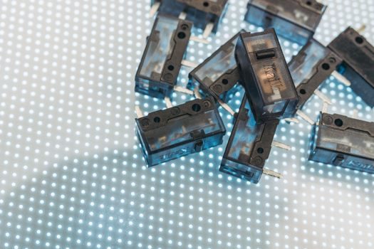
Skip fiber optic when the target is large, metallic, and the environment is benign — an inductive sensor will be cheaper, more robust to fiber damage, and free of glass fragments as a maintenance hazard. Skip inductive when the target is non-metallic, when sub-millimetre resolution is required, or when the sensing point is inside a hazardous or high-temperature zone that demands an intrinsically safe, dielectric-only penetrator [S1][S2].
For hybrid cells — say, a metal screw on a hot die — a fiber optic through-beam pair with heat-resistant glass fibers and a remote amplifier is the standard answer, and a fiber converter topology lets the same amplifier drive a long fiber run back to a control cabinet without signal loss.
Two signals to watch into the back half of 2026: IO-Link integration of fiber optic amplifiers (still patchy versus the near-universal IO-Link coverage on M-series inductive sensors) and the migration of plastic fiber tips into 80 °C-plus under-hood automotive and battery-cell lines, where the temperature headroom of the remote amplifier, not the fiber, is now the binding constraint [S2][S4][S5].
Spec-level background on the components involved: fiber optic sensor.