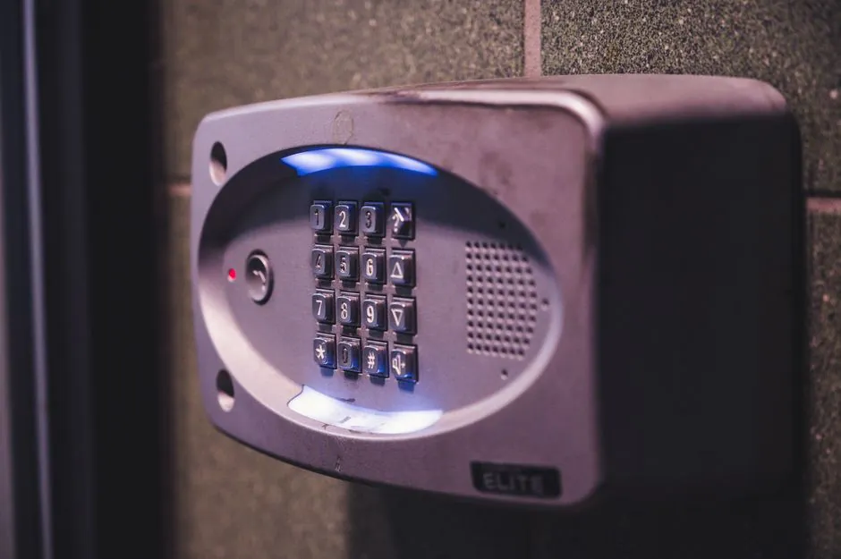
A fire alarm control panel can initiate HVAC shutdown through an interposing relay, with the panel energizing the relay coil and the relay contacts switching the fan or unit-control circuit.
For systems with design capacity above 2,000 cfm, smoke detection and air-distribution shutdown must be checked against the governing code, while relay listing, supervision, polarity, and fail-safe behavior require project-specific verification [S3].
How the HVAC shutdown signal passes through the fire alarm panel
A fire alarm relay module accepts a low-energy control signal and uses it to switch a separate circuit that powers or controls a larger device, including an HVAC fan starter, actuator, or packaged-unit control circuit [S1][S3].
The operating sequence has three distinct elements: the panel output energizes the relay coil at the panel voltage, the relay contacts operate at their own circuit voltage, and the controlled HVAC circuit opens to stop the fan or remove power from the actuator [S3]. This separation matters because a panel relay output or addressable control module has limited contact capacity and should not be assumed suitable for direct line-voltage switching.
Two control arrangements are possible. The relay may be energized during normal operation and de-energized at alarm, or it may remain de-energized until the alarm output energizes it [S3]. The choice determines whether loss of relay-coil power causes shutdown, but it does not by itself prove that the complete installation is fail-safe. Loss of wiring, contacts, control voltage, or panel output must be addressed by the approved sequence.
UL864 and UL916 are not interchangeable listings
UL 864 covers control units and accessories for fire alarm systems, whereas UL 916 covers energy-management equipment; a UL 916 listing does not establish suitability for connection to a fire alarm system [S3].
Where the Authority Having Jurisdiction requires fire-alarm use, the interposing relay generally needs a UL 864 listing [S3]. Functional Devices identifies the RIBU1C as UL 916-listed for energy management and the RIBU1C-RD as its UL 864-listed counterpart [S3]. This distinction is not a minor paperwork issue because it defines whether the relay has been evaluated for the intended fire-alarm application.
Local requirements can add another approval layer. For example, fire alarm devices sold in California may require approval by the California State Fire Marshal [S3]. Before purchasing relays, the project specification, panel output type, relay contacts, coil voltage, current, and required listing should be checked against the Authority Having Jurisdiction. A general-purpose relay can be electrically capable yet unsuitable for the required life-safety interface.
Relay types compared against shutdown and listing criteria
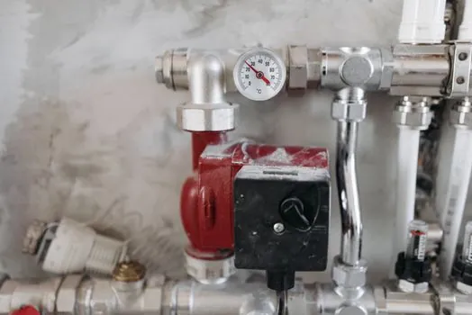
Where the Authority Having Jurisdiction requires an interposing relay to be listed for fire alarm use, it must carry a UL864 listing, which a general-purpose UL916 relay does not provide.
The comparison is criteria-based: interposing isolation protects the panel output, UL 864 addresses the fire alarm listing question, direct contacts reduce equipment count, and addressable modules support selective control. None can be selected from relay function alone; contact ratings, circuit voltage, listing, and shutdown logic remain decisive [S3][S5].
Airflow threshold, detection location, and shutdown scope
The International Mechanical Code requires smoke detectors in return-air systems with design capacity greater than 2,000 cfm, located in the return duct or plenum upstream of filters, exhaust-air connections, and outdoor-air connections under IMC 606.2.1 [S3].
Where multiple air handlers share a common supply or return and their combined capacity exceeds 2,000 cfm, IMC 606.2.2 subjects the shared system to the same detection requirement, and IMC 606.4 requires shutdown of the air-distribution system on detector activation [S3].
A complete shutdown sequence can include more than stopping the supply fan. The same interposing arrangement can remove power from smoke-damper actuators and magnetic fire-door holders, while the related fire door hardware must be addressed by the approved design. The smoke detector that initiates shutdown and the fire alarm control panel that processes the event should both be included in end-to-end functional testing.
Supervised wiring, polarity, and fail-safe behavior
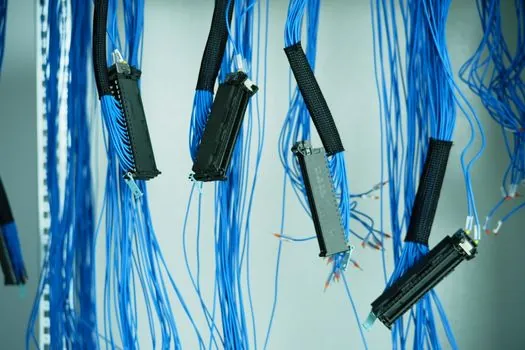
A supervised relay circuit can present voltage at its terminals without energizing the relay, allowing the fire alarm control panel to monitor wiring integrity rather than relying on terminal voltage alone [S4].
Reverse-polarity supervision changes the circuit condition used to operate the relay. In the described installation, a relay board remained powered in both standby and alarm conditions, but the polarity changed so the coil could operate only in the alarm condition [S4]. Terminal voltage therefore did not, by itself, indicate that the relay had changed state.
The documentation must identify the relay state in each condition. Normally open contacts can keep the HVAC unit running while the relay is energized, but if the relay is continuously powered and drops out on alarm, a wiring failure may also remove the relay state needed for shutdown [S4]. The approved sequence must define operation for fire alarm, supervisory trouble, power loss, reset, and manual test. Smart integration also requires alarm and supervisory states to be mapped separately so a trouble condition does not create the same HVAC response as a confirmed alarm [S2].
Commissioning tests that expose hidden integration faults
Commissioning should test the complete path from initiating device to final HVAC state, including relay-coil voltage, contact state, fan-stop result, actuator response, indication at the panel, and restoration after reset [S2][S3].
At least four checks are required. First, operate the initiating smoke detector and confirm that the designated air handler stops rather than only confirming a relay LED. Second, verify that the relay performs the approved transition in both normally energized and de-energized designs. Third, simulate the supervised wiring or polarity condition and confirm the intended trouble response without producing an unintended shutdown. Fourth, exercise reset and verify that HVAC restart follows the approved sequence rather than an automatic restart at an unsafe time.
Each test should record the initiating address or zone, panel output, relay identification, HVAC unit, pre-test state, alarm-state result, trouble-state result, and restoration method [S2]. The same relay controls smoke dampers or door-holder power, the test must also confirm those outputs because a successful fan-stop result alone does not prove correct end-to-end shutdown [S3].
Where direct outputs, interposing relays, and addressable modules fit
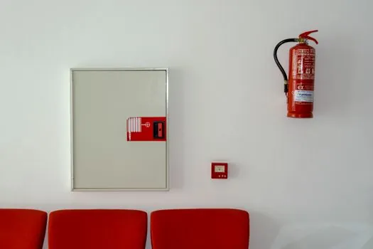
Direct panel outputs are suitable only when the listed panel relay has sufficient contact ratings for the controlled circuit, whereas an interposing relay isolates a line-voltage HVAC circuit from a low-energy panel output [S3].
Relays are appropriate where a simple, repeatable on-off shutdown action is required, but their implementation must still distinguish alarm, trouble, reset, and power-loss behavior [S1][S4]. Addressable control modules are preferable where the panel must identify and command individual outputs, because separate modules can be controlled through one signaling line circuit and selected according to the initiating input [S5].
The system is not for unapproved equipment shutdown outside the fire-life-safety design. It should not be treated as a general building-automation bus, and an energy-management relay should not be substituted for a required fire alarm relay. The fire alarm control panel output remains the authority for the emergency action, while relay logic translates that command into the electrical action required by the HVAC equipment.
The next trackable signal is the approved cause-and-effect matrix: it should identify every initiating detector, panel output, relay, HVAC unit, damper, door holder, alarm polarity, trouble polarity, and reset action. Relay submittals should then show coil voltage, contact ratings, contact form, UL 864 listing when required, and the AHJ approval path before installation.