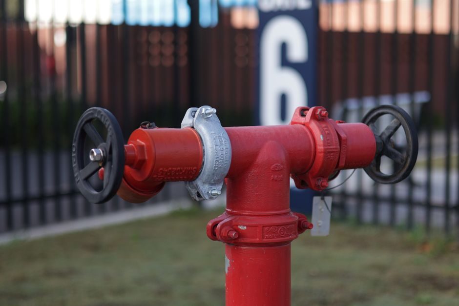
Hydrant installation fails at acceptance when bury depth, barrel class, isolation-valve location, and thrust-block sizing are not resolved before the trench opens, because AWWA C600 / C602 and NFPA 24 inspect all four in the same walk [S4].
This guide covers dry-barrel and wet-barrel hydrants on municipal water mains, including the criteria that decide type, bury depth, valve placement, thrust-block sizing, and the color-code mapping under NFPA 291. It is written for civil and mechanical engineers responsible for submittal packages, water-authority inspectors, and EPC contractors running the actual install.
Definition, Scope, and the Standards That Bind the Work
Fire hydrant installation means assembling an above-ground outlet assembly, a barrel, a shoe with an integral or attached main valve, and a connection to a pressurized water main, then testing and marking it to AWWA, NFPA and the local water-authority standard. Dry-barrel units dominate where frost penetrates the bury depth, and wet-barrel units stay restricted to warm-climate, non-freezing networks, because the main valve on a dry-barrel hydrant sits below the frost line and drains the barrel after each use [S4].
Four documents cover most municipal installs in North America: AWWA C600 for the underground installation of potable water mains and their appurtenances, AWWA C602 for cement-mortar lining of the connecting pipework, NFPA 24 for private and public water-service mains and their hydrants, and NFPA 291 for fire-flow testing and the color coding that maps available flow to bonnet and cap paint. The local water authority (DC Water, NYC DEP, LA DWP, etc.) almost always imposes additional detail on bury depth, valve spacing, and tapping-saddle use, and that detail overrides the model spec when the two conflict. A working fire hydrant types and classifications spec map is the right first read before this install guide, because the type chosen upstream sets the flange class, hose-nozzle thread, and valve geometry that the trench has to accommodate.
Selection Criteria: Type, Bury, Valve, and Barrel Class
Pick the hydrant type by climate and flow class first, then size the bury and barrel; reverse that order and the trench will be re-dug. Dry-barrel AWWA C502-compliant hydrants are the default anywhere the frost line is deeper than the run-off drain, and the pressure class on the nameplate (Class 150 / 250, with 250 psi working / 500 psi test the common rating on modern C502 hydrants) has to equal or exceed the system's static plus surge pressure. [S2]
The decision matrix for the trench side:
1. Type: dry-barrel (AWWA C502) where frost penetrates the trench, wet-barrel (AWWA C503) only in non-freezing zones; breakaway traffic-model hydrants are required where the hydrant sits inside the curb radius or inside a roadway clear-zone.
2. Bury depth: standard 5 ft (1.5 m) bury covers most of the central and southern U.S.; 6 ft (1.8 m) bury covers the northern tier; 7 ft (2.1 m) and deeper is specified in cold regions. Measure from the finished grade line at the hydrant base to the invert of the connecting main, not to the bottom of the trench.
3. Barrel class: ductile-iron barrel and shoe per AWWA C502; flanged shoe connection is preferred over all-buried mechanical joint, because it lets the main valve seat be serviced without cutting the barrel.
4. Nozzle and thread: 4.5-inch (114 mm) pumper nozzle + two 2.5-inch (64 mm) hose nozzles is the North American default; the hose-nozzle thread standard is NH (National Hose) unless the authority of jurisdiction specifies NST, NPT or local fire-department threads (NYC uses New York Corp; Boston uses the Boston special).
5. Operating nut and direction: open left (counter-clockwise) is the East Coast and federal standard, open right (clockwise) is common in the South and West; confirm with the authority having jurisdiction before the hydrant is ordered, because operating nuts are not interchangeable in the field.
Site Prep: Location, Clearance, and Thrust-Block Logic
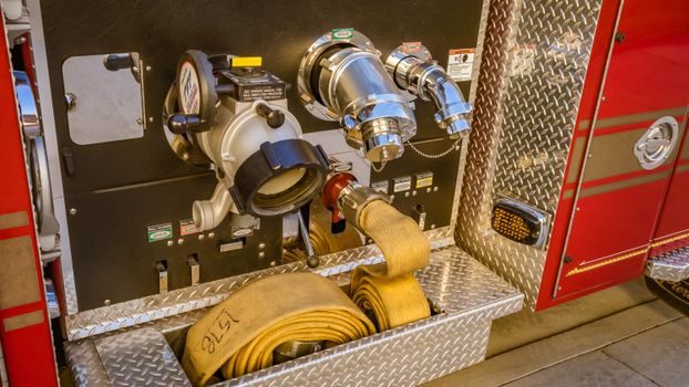
Locate the hydrant no closer than 2 ft (0.6 m) from a curb, no closer than 5 ft (1.5 m) from a building face, and on a 3 to 5 ft (0.9 to 1.5 m) setback from the traveled way, with the pumper nozzle facing the street; this is the working clearance that lets a fire engine connect without parking on top of the hydrant. Set the hydrant on a 12 in (300 mm) thick crushed-stone or concrete pad so the drain holes do not seal against native clay, because a hydrant that cannot drain will freeze and split the barrel the first winter. [S2]
Thrust at the hydrant tee and at any direction change on the connecting main must be restrained with concrete thrust blocks bearing against undisturbed soil, sized to the soil's allowable bearing capacity (typically 1,500 to 3,000 psf for stiff clay, 4,000 to 6,000 psf for dense sand and gravel). On plastic mains, AWWA C605 and the pipe manufacturer require restrained mechanical-joint glands or an entire-length of restrained joint pipe on either side of the tee, because the concrete block alone does not transfer the surge load from HDPE or PVC. The isolation valve is placed on the main directly between the hydrant tee and the run-of-main, within 25 ft (7.6 m) of the hydrant base, so a shutoff for hydrant repair does not require closing the entire branch.
Trench width at the hydrant base is the barrel OD plus 12 in (300 mm) working clearance on each side, and depth is the invert of the connecting main plus the required bedding thickness, which is typically 6 in (150 mm) of granular material below the main invert. Compaction under and around the shoe to 95% Standard Proctor before the hydrant is set vertical, then recheck plumb after backfill is placed, because a hydrant set vertical in the trench commonly ends up leaning 1 to 2 degrees after backfill compaction, and a leaning hydrant is an automatic reject on a water-authority punch list.
Installation Sequence and Hydrostatic Acceptance
[S2]
Hydrostatic acceptance is the binary pass/fail: 2 hours at test pressure, with allowable leakage on the hydrant assembly (valve, lead, fittings) of zero gallons per hour — any visible weep at the flange, the drain, or the operating stem is a fail. The drain holes on a dry-barrel hydrant have to be tested separately by capping the outlets, pressurizing the barrel, then watching the drain flow; a dry barrel that does not drain within 60 seconds of pressure release is a fail and the hydrant must be reset on a stone pad. For municipal installs, the local water authority inspector witnesses both tests and signs off before backfill above the hydrant base, so schedule the test in advance and keep the trench open until the inspector is on site.
NFPA 291 Color Code, Flow Class, and Field Marking
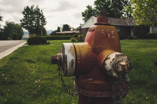
Color code the bonnet and the 2.5-inch caps to the available flow at 20 psi residual, per NFPA 291: light blue for 1,500 gpm and above, green for 1,000 to 1,499 gpm, orange for 500 to 999 gpm, red for less than 500 gpm. The flow test itself runs one hydrant upstream flowing, one hydrant downstream (or the test hydrant) at residual, with pitot readings on a smooth-bore nozzle or a calibrated pitot-less flowmeter, and the result posted at the hydrant or in the authority's GIS. The 4.5-inch pumper cap is left unpainted chrome or painted to match the barrel, depending on the local convention. [S2]
Where the local water authority also requires a blue raised pavement marker (RPM) in the lane nearest the hydrant, install it 6 to 12 in (150 to 300 mm) off the centerline on the lane side, so a fire engine approaching the hydrant can spot it from 100 ft (30 m). Tag the hydrant with the authority's GIS ID and a QR or barcode label on the operating nut cap, because field crews that can scan the hydrant from a tablet cut the time to find the isolation valve by 60 to 80 percent on a real outage. The flow-test and color-code data feed the fire hydrant types reference that dispatch systems use to route the right pumping engine, so a hydrant with the wrong color is a routing problem, not a paint problem.
Failure Modes, Common Punch-List Defects, and When to Re-Set vs Replace
Most hydrant acceptance failures fall into five categories. (1) Leaking flange: re-torque to the flange bolt spec (typically 70 to 90 ft-lb for a 5/8-inch bolt on a Class 150 flange); if the gasket is extruded, reset the hydrant and replace the gasket. (2) No drain flow after pressure release: the stone pad has migrated into the drain holes or the hydrant was set on native clay; reset the hydrant on a fresh 12 in stone pad and re-test. (3) Hydrant leaning more than 1 degree from vertical after backfill: excavate one side, re-plumb, and recompact in 6 in lifts. (4) Operating nut binding: the operating stem extension is misaligned with the main valve stem; reset the hydrant, do not try to grind the nut to fit, because a stripped operating nut means a hydrant that cannot be opened under fire-flow conditions. (5) Wrong flow-class color after the first flow test: repaint to the actual flow class, do not leave a hydrant under-classed because the color was easier to source. [S2]
Replace the hydrant, do not repair, when the barrel shows a through-wall crack, the main valve seat is pitted beyond the manufacturer's re-grind spec, the operating stem threads are stripped, or the shoe flange is corroded below the minimum wall. A through-wall crack on a ductile-iron barrel is a structural reject regardless of where it sits along the barrel, because the crack will propagate under surge and the hydrant will split during the next fire-flow event. Where the failure is downstream of the isolation valve, the fix is on the lead; where it is upstream of the valve, the fix is on the main, and the hydrant can stay in service if it passes its own pressure test.
Commissioning, As-Built, and Hand-Off

Hand the hydrant off with five documents: the AWWA / NFPA hydrostatic test report, the NFPA 291 flow-test sheet with the calculated available gpm and the color code, the valve-isolation card with the valve size, type, depth and turn count, the backfill-compaction log, and the GIS update with the as-built GPS, depth, and branch-tee orientation. The water-authority inspector signs all five before the hydrant is put in service, and the fire-prevention bureau of the local fire department cross-checks the GIS against its pre-plan maps, because a hydrant on the GIS that the fire department's pre-plan does not show will not get pumped to in a real fire. [S2]
Trackable signals for the next six months: AWWA / NFPA standards committee ballots on C502 and C600 (typically one comment-cycle per year), local water-authority hydrant-spec revisions, and the fire department's hydrant-flow retest cycle, which most authorities run annually. Two follow-up reads pair well with this install map: the fire hydrant types spec map for choosing the right hydrant before trenching, and the fire extinguisher TCO and 10-year lifecycle map for the related water-based suppression equipment that shares the same water supply.
Spec-level background on the components involved: linear guide, and crossed roller guide.