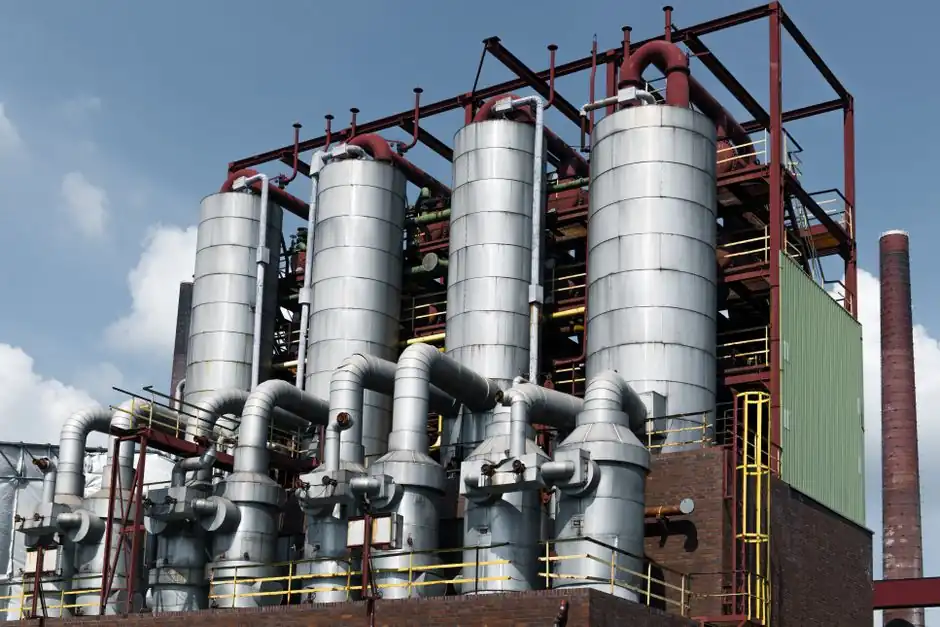
Steel mill drives demand fluid couplings that absorb hammer loads, tolerate ambient heat near reheat furnaces, and protect gearboxes on coilers, roller tables, and sinter conveyors [S1][S4].
Why a Fluid Coupling, Not a Gear Coupling, on a Mill Drive
A fluid coupling transmits power through hydraulic fluid between a pump impeller and a turbine runner inside a sealed housing, with no mechanical teeth in the load path [S6][S7]. This hydrokinetic principle lets the slip absorb the peak torque spike of a coil entry or a tonnage surge, then transfer steady-state torque once the driven train is up to speed [S6].
Helical gear couplings, by contrast, transmit torque through meshed teeth and are sized for high-torque constant-load mill service such as heavy rolling-mill main stands and turbine drives [S3]. For variable load and shock conditions, the gear coupling passes the impact straight through, which is why the typical mill conveyor, sinter cooler, and coiler drive train places the fluid coupling upstream of the gearbox and the helical disc or jaw coupling element downstream [S3][S4]. This staged arrangement isolates the gearbox input from the motor's locked-rotor transient and from the load's worst torque event [S4].
Mill Operating Profile: Heat, Dust, Vibration, Ambient
Steel mill auxiliaries run hot, dirty, and mechanically noisy. Sinter plants, coke-handling conveyors, and continuous-cast cooling beds sit in ambient conditions that can climb above 40 °C, with iron-oxide dust and structural vibration degrading any seal or bearing that is not rated for the environment [S1]. Under these conditions, the wrong coupling runs hot, sheds seal life, and accelerates gearbox wear; a correct selection derates the coupling, specifies a higher-temperature seal kit, and uses a heavy-duty casing [S1].
Mill conveyor duty cycles also concentrate thermal load inside the coupling. If the fluid coupling is run outside its rated power band, the internal hydraulic slip multiplies, fluid temperature rises, seal life falls, and the unit can scald the driven gearbox [S1]. Choosing a unit with a thermal capacity matched to the mill's start-per-hour cycle, not just the running kW, is the difference between a 20,000-hour life and a 6,000-hour life on a hot-strip coiler rewind stand [S1].
Sizing Logic: Power, Slip, Starting Torque, Service Factor
Mill selection reduces to four numbers: motor kW, service factor for the driven machine, required starting torque as a percentage of full-load torque, and maximum slip under the worst shock event [S5]. A mill coiler rewind typically runs at 150-180% starting torque to wind the first wraps without snapping the strip, a sinter cooler fan runs at 120% to limit motor inrush, and a crusher on a slag granulator line runs at the top of the band, near 250% [S5].
Service factor is where mill practice diverges from lighter industry. A furnace-charging conveyor or a coke-quench car drive should be treated as a heavy-shock load class, and the coupling selected one size above the motor nameplate kW, not at the catalogue running point [S1][S4]. Variable-speed fluid couplings used for pump, fan, and compressor speed control span 100 kW to 35 MW in current OEM offerings, with the mill-auxiliary range sitting comfortably in the lower half of that band [S2].
Comparison: Constant-Fill vs Variable-Fill vs Elastomeric Couplings
Three options compete for the same mill drive slot: constant-fill fluid coupling, variable-fill (or scoop-controlled) fluid coupling, and elastomeric element coupling [S3][S5]. On the criteria that matter to a mill maintenance engineer, the comparison is sharp.
Constant-fill fluid coupling: lowest cost, no control circuit, fixed starting torque at 120-250% of full load, simple thermal management, and the most common fit on conveyors, pumps, and fans in cement, mining, and steel [S4][S5]. Variable-fill fluid coupling: an external scoop or working chamber varies fill level on the fly, giving speed control under part-load, used where a furnace ID fan or a sinter cooler fan needs damped turndown, and supports the wider 100 kW to 35 MW power band [S2]. Elastomeric shaft coupling or coupling clutch element: cheaper still, but transmits shock directly to the gearbox, and is rejected on mill coilers, slag crushers, and any drive where a single jam would otherwise strip the input pinion [S3].
For the highest-shock mill positions, the fluid coupling sits in series ahead of a gear coupling or jaw coupling at the gearbox input, splitting the shock absorption (fluid) and the misalignment tolerance (mechanical element) between two purpose-built devices [S3][S4].
Failure Modes and Selection Mistakes to Avoid

The three failure modes most often traced back to wrong coupling selection in steel mills are thermal overload, gearbox shock fatigue, and unplanned shutdown [S1]. Thermal overload shows up as discoloured fluid, hardened seals, and a coupling that runs 20-30 °C above the rated bulk-fluid temperature; it is almost always a case of under-sized fill or excessive start-per-hour duty [S1].
Gearbox shock fatigue shows up as spalled input pinion teeth, fractured bearing races, and sheared input shaft keys; it is the signature of a coupling that was rated for steady-state torque but not for the mill's lock-rotor or jam-clear event [S1][S4]. Unplanned shutdown is the visible symptom: a coupling that burned up, a gearbox that stripped, a line that stopped for the day. Avoiding all three means derating for ambient, derating for shock, and sizing the fluid coupling as a system with the gearbox and driven machine, not in isolation [S1].
Standards, Sourcing, and Procurement Timing
Mill procurement teams should anchor the spec on power band, starting-torque band, thermal capacity, and ambient rating, then verify that the chosen unit meets the drivetrain's existing service factor [S1][S5]. For a typical sinter plant or hot-strip mill auxiliary, count on a 6-12 week lead time on a constant-fill fluid coupling and longer on variable-fill units with integrated oil cooler and scoop actuator [S2]. Sourcing decisions for long-lead mill turnarounds are best made 4-6 months ahead of the planned outage; the pattern matches broader industrial practice on drivetrain hardware, and aligns with the early-procurement playbook discussed for fast-track industrial projects.
Two trackable signals to watch through the next two quarters: OEM disclosure of thermal-derating curves at 50 °C and 60 °C ambient for mill-grade fluid couplings, and any movement on the 35 MW upper bound of current variable-speed fluid coupling product lines [S2]. If either shifts, mill spec sheets on hot-strip coiler and sinter cooler fans will need to be revisited within the next revision cycle.