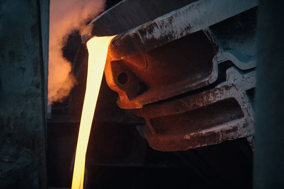
Steel mill drives are sized around three numbers: peak torque at the moment of roll bite (3-5x steady-state, occurring in milliseconds), ambient temperature near furnace areas (60-80C baseline, pushing 150C at the hottest zones), and contamination load from mill scale and metal dust below 10 microns in particle size [S2][S3].
Rolling mill motors commonly run 3,000-12,000 hp, but nameplate power alone is a poor sizing input; the gearbox must absorb instantaneous loads that far exceed it, which is why service class III (AGMA service factor 2.0 or higher) is treated as the floor, not a luxury margin, for primary mill drives [S3]. A gearbox selection for cement plants comparison is useful for engineers who also run kiln and raw-mill conveyor lines, since the dust and continuous-duty profile overlap heavily with steel mill auxiliaries.
Service Factor Math for Real Mill Duty
Mill duty selection uses SF = F x C, with the calculated SF held below the gearbox rated fB, otherwise the next frame size is required [S2]. The F-value table treats uniform loads at F = 1.0 (cooling-water pump, steady exhaust fan) and moderate-shock 24 h/day duty at F = 1.4 (continuous casting strand drives), but rolling-mill bite spikes fall outside both bands and demand a correction factor C for starts per hour on top of F [S2].
The practical consequence of underrating F is documented: a Thailand bar mill that stepped from a 300 kW to a 600 kW motor to roll thicker billets lost its helical gear at 15,000 hours against an expected 40,000-50,000 hours, with failure analysis showing contact-stress fatigue after the service factor was never recalculated for the new input power [S3]. Engineers who only match gearbox rating to motor nameplate, ignoring peak load, are consistently seeing tooth wear and bearing fatigue at roughly half expected service life [S2].
Gearbox Type Comparison by Mill Application
Planetary units dominate high-torque, compact-footprint applications such as rolling-mill main drives and heavy conveyor headshafts, because load is shared across multiple planet gears and torque density per envelope is the highest of the four common architectures [S1]. Bevel-helical units are the default where the drive shaft must turn 90 degrees, which is the geometry of most cooling-bed and transfer-carriage drives [S1].
Helical gear motors cover auxiliary steel mill equipment (material handling conveyors, coil transfer, scrap handling) where smooth, quiet operation outweighs the need for a right-angle output [S1]. Heavy-duty spur gearboxes still show up in older rolling-mill drive lines where mechanical simplicity and a strong straight-cut tooth engagement outweigh efficiency losses; they are not the right pick for new reversing-mill duty where torque reversal under load is routine [S1][S2].
Housing, Material and Bearing-Side Specs

Helical gear motor housings in mill duty are high-quality cast iron with fine-bored bearing seats machined on a CNC machining center, because bearing-seat accuracy directly controls how the gears mesh under cyclic peak load [S2]. Standard welded or fabricated housings do not hold the bore geometry required for AGMA class III life.
Sealing is a separate line item: 82% of machine wear is particle-induced (Society of Tribologists and Lubrication Engineers / National Research Council of Canada), and the wear-causing fraction in a mill is sub-10-micron scale and metal dust that passes through standard breathers [S3]. For mill duty, IP65 (fully dust-tight, water-jet resistant) is the minimum and IP66 (powerful water-jet resistant) is preferred where washdown is part of the housekeeping routine [S3]. A stainless steel hardware set on the breather, drain, and inspection covers is a common retrofit to cut corrosion loss on the gearbox envelope.
Load Signature and What it Does to Bearings
On a reversing rolling mill, direction changes happen under full load, so the gearbox teeth see full torque reversal, forward to reverse, within fractions of a second; backlash management and tooth geometry have to be tighter than for almost any other industrial gearbox application [S2]. The bite transient is not a bump, it is a sharp, repeating spike at the work-roll rotation frequency, and the fatigue accumulation over millions of cycles is what kills bearings and gear teeth first.
For reversing-mill duty, the spec typically includes oversized shaft diameters, case-hardened and ground gears, and tapered-roller or spherical-roller bearing arrangements sized to absorb both radial and axial shock, rather than the deep-groove ball bearings common in general industrial units. Cyclic peak torque on roughing stands frequently reaches 3-5x steady-state, so the shaft and coupling selection must be reviewed against the same peak, not against motor rated torque [S2][S3].
Common Failure Modes and What They Tell You

The four failure patterns that show up repeatedly in mill gearboxes are: (1) contact-stress fatigue on the gear tooth flank from a service factor that was never raised when motor power was upgraded, the Thailand bar mill case [S3]; (2) bearing fatigue from sustained F = 1.25 sizing in an application that genuinely required F = 1.7 plus starts-per-hour correction [S2]; (3) seal and breather bypass by sub-10-micron scale, visible as accelerated oil contamination and elevated bearing temperatures [S3]; and (4) oil-thermal breakdown from continuous duty at 60-80C ambient, which shortens additive life and pushes the lube toward oxidation faster than the standard change interval assumes.
Each of these is detectable before catastrophic failure if vibration analysis, oil sampling, and thermal trending are part of the routine. A marine slewing bearing selection spec map shares the contamination-driven sealing logic, useful for engineers who also spec outdoor or washdown-exposed drives.
Standards, Sourcing, and Sizing Inputs to Lock Down
The governing reference for service class and load classification is AGMA, with service class III (SF 2.0) the minimum target for primary mill drives and class I/II units rejected at the spec stage [S3]. Service factor calculation must include the load-type factor F (from application and hours per day), the starts-per-hour correction C, and the resulting SF checked against the gearbox rated fB; if SF exceeds fB, step to the next frame size rather than accept a derated margin [S2].
Engineers should also lock down the F-value with the specific application in writing: uniform load F = 1.0, moderate shock 24 h/day F = 1.4 (continuous casting strand drives), and primary rolling-mill bite duty above that band with the C-correction on top, not a generic "heavy shock" label pulled from a catalog [S2]. For procurement, frame size, service factor, IP rating (IP65 minimum, IP66 preferred), housing material (high-quality cast iron, CNC-finished bearing seats), and lube spec should all be written into the purchase spec, because none of them can be retrofitted cost-effectively after the unit is on the floor.
Detailed specification references: gearbox, and alloy steel.