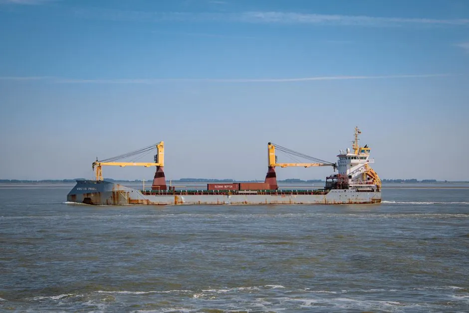
Marine crane slewing bearings are specified as 011/012 external-gear or 013/014 internal-gear four-point contact ball units in the 200 mm to over 6,000 mm diameter band for knuckle-boom and deck cranes, with double-row ball or three-row roller structures required for hose-handling, offshore, and heavy-deck duty after a full load-case review that includes vessel list, trim, roll, pitch, and heave [S1][S4].
The global market for these components stood at roughly USD 4.8 billion in 2023 and is projected to reach USD 7.2 billion by 2033 at a 5.3% CAGR, with over 78,000 large construction cranes already dependent on slewing ring technology for 360° rotation, and offshore wind and offshore heavy-lift cranes consume a meaningful slice of that installed base [S1]. For shipboard specification, the engineering difference from a land crane is not the bearing geometry, which is the same slewing bearing architecture, but the corrosion protection, sealing, ship-motion load cases, and classification documentation wrapped around it [S4].
Ship-Motion Load Cases Drive Bearing Selection
At sea, static list and trim rotate the load vector, while roll, pitch, and heave add accelerations that are absent from any calm-water chart, so the bearing review must combine the crane's own load cases with agreed vessel-motion and dynamic parameters before type is fixed [S4]. Knuckle-boom and general-deck cranes commonly start with 011/012 external-gear or 013/014 internal-gear four-point contact ball structures, while larger hose-handling cranes, offshore units, and heavy-deck applications may require double-row ball or three-row roller structures after a full load review, because the radial, axial, and tilting-moment combinations at sea often exceed what a single-row ball unit can carry with acceptable reserve [S4]. Raceways on marine units are surface-hardened to HRC 55–62 against rolling contact fatigue, and the rings themselves are typically 42CrMo4 medium-carbon alloy steel, which is the same material baseline as land units, but the selection logic differs because the load envelope keeps moving [S1][S4].
Corrosion Protection Is Its Own Specification, Not an Accessory
Barge and deck cranes sit inside a salt-laden wet zone even when idle, so wind-driven spray, washdown water, and condensation all collect around the pedestal joint and demand a documented marine coating system on exposed ring surfaces plus compatible preservation on machined mounting faces, bolt interfaces, and gear teeth [S4]. The sealing review should specify a primary elastomer seal, a protective flinger or secondary barrier, positive drainage, and grease-purge paths that expel moisture rather than trapping it against the raceway, and greasing intervals in the crane manual should include a full-rotation relube procedure to push fresh grease outward through the seal [S4]. Small details matter at sea: grease fittings, plugs, fastener interfaces, and unused tapped holes need their own corrosion-resistant specification, because exposed steel on these small items becomes the corrosion initiation point that later migrates into the slewing ring bearing interface [S4].
Classification Documentation Is a Deliverable, Not a Promise
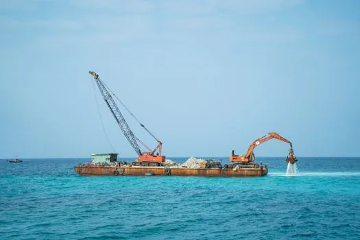
Marine cranes are typically built under DNV, ABS, Lloyd's Register, Bureau Veritas, RINA, or another classification society selected for the vessel, and the bearing inspection and documentation package must be agreed with the crane manufacturer and survey plan before production begins [S4]. The deliverable typically includes EN 10204 3.1 mill certificates, dimensional and clearance reports, raceway hardness and effective case-depth results, full material traceability, and specified ultrasonic or magnetic-particle testing, and where EN 10204 3.2 or third-party witnessed inspection is required, hold points, witness points, responsible parties, and document formats should be fixed at order so surveyor attendance does not delay production [S4]. Factory and supplier qualification records, plus customer visit logs, are usually verified by the marine customer before order placement, because the bearing is part of the crane technical file and the survey chain cannot be retrofitted after the ring is welded into a pedestal [S4].
Single-Row Ball vs Double-Row Ball vs Three-Row Roller vs Crossed-Roller
Four-point contact ball slewing rings (single-row ball, the 011/012 external-gear and 013/014 internal-gear marine family) carry combined axial, radial, and moment loads in one raceway, which keeps weight, height, and cost down for typical deck-crane duty [S1][S4]. Double-row ball designs add a second row of contact, lift load capacity, and are preferred on heavy-duty cranes where single-row reserve is too thin, while three-row roller structures place a separate roller row for each load direction and are the marine default for large hose-handling, offshore, and pedestal-mounted heavy-lift cranes after the full load review [S1][S4][S5]. Crossed-roller slewing rings, exemplified by series-08 units such as the XSU080218 (180 mm bore, 0.025 mm bore upper tolerance, lamellar seals both sides, no gear teeth), use cylindrical rollers crossed at 90° for high stiffness and precision in a compact section, and are typically reserved for tighter-radius, higher-precision positioning duties rather than the largest offshore pedestals [S6]. Balls make point contact (lower friction, well-suited to multi-directional load mixes) while rollers make line contact (higher load per element, better for heavy unidirectional duty), so the ball-versus-roller decision is a direct consequence of the ship-motion load envelope rather than a free design choice [S1].
Failure Modes and Common Pitfalls at Sea
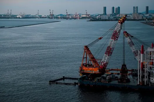
The dominant failure modes on marine slewing bearings are not the load-rupture events that dominate land duty, but corrosion-driven raceway pitting, seal degradation that lets salt water reach the rolling elements, and grease channeling that traps moisture against the raceway instead of purging it outward [S4]. Specifiers who treat the marine project as a land project with extra paint typically discover, within the first yard or two of operation, that the raceway surface hardness (HRC 55–62) was preserved but the seal interface and gear teeth have corroded, which then distorts the gear mesh and loads the slewing drive pinion unevenly [S1][S4]. The other recurring pitfall is accepting the bearing certificate without aligning the hold points, witness points, and document formats with the classification society at order, which forces retrospective inspection and can delay the crane technical file long after the ring is in place [S4].
What Specifiers Should Send to the Bearing Supplier
A marine bearing review cannot start from a generic data sheet; it needs operating and survival load cases, vessel list and trim limits, vessel accelerations, full boom-position envelope, lifted load spectrum, and any classification-society factors agreed for the crane design, all handed to the bearing supplier alongside the corrosion-protection specification and the agreed inspection scope [S4]. For heavier offshore or hose-handling duty, the spec should also flag whether a double-row ball or three-row roller structure is being considered, because that decision changes ring thickness, gear geometry, and bolt-pattern layout, and it must be locked before the bearing drawing is released [S4]. Cross-checking the selection logic against a steel-mill duty case, where load and heat are the drivers, is also worthwhile; a parallel steel-mill slewing bearing selection map makes the contrast between thermal-driven and corrosion-driven specification explicit, and the same geometry language applies across both [S1][S4].
Selection Criteria Summary for Marine Crane Slewing Bearings

For deck-crane duty, the baseline is a single-row four-point contact ball unit in the 011/012 external-gear or 013/014 internal-gear configuration, 42CrMo4 rings, raceways at HRC 55–62, with a documented marine coating system, elastomer primary seal plus secondary barrier, and EN 10204 3.1 documentation; for offshore, hose-handling, or heavy-deck duty, the minimum steps up to a double-row ball or three-row roller structure with the same material and hardness baseline but thicker sections, and EN 10204 3.2 or third-party witnessed inspection is commonly added to satisfy the class surveyor [S1][S4]. Gear selection is driven by static strength, pitting resistance, and fatigue of the gear/pinion interface, and is specified together with the bearing type rather than as a separate item [S1][S5]. For applications that need precision and stiffness in a compact section, crossed-roller series such as the XSU080218 (180 mm bore, no gear teeth, lamellar seals both sides) are the alternative, but they sit outside the main offshore-deck envelope and are typically selected for tighter-radius positioning rather than full pedestal load [S1][S6].
Trackable signals to watch on the next ordering cycle are: classification-society hold-point and witness-point definitions being locked into the supplier QA plan at order entry, not at delivery; EN 10204 3.2 upgrade requests becoming routine on offshore-deck tenders; and three-row roller marine units displacing single-row ball units on new hose-handling crane platforms once the load-case review confirms the heavier envelope.