
A correctly designed stuffing box for gland packing is dimensioned as a multiple of the packing cross-section W, with a total depth of 5W when no lantern ring is used and 7W when one is fitted, split 2W on the pressure side and 3W on the gland side [S1]. The lantern ring itself is sized at 2W length, and the gland take-up must be capped at 40% of the packing's free height to keep the shaft from galling before the gland goes fully tight [S1].
Under those geometric rules, a properly broken-in pump packing set is expected to leak at 8-10 drops per minute per inch of shaft (Klinger's preferred figure) or 10-12 dpm per inch (SEPCO's working envelope), which is the controlled leakage that cools and lubricates the interface [S1][S3]. Both numbers describe the same physical target: enough film to carry heat away, not so much that the seal has stopped doing its job.
Stuffing box geometry: W, depth, chamfer, gland length
W is the cross-sectional width of the packing ring, and the stuffing-box table published by Klinger ties W directly to shaft diameter: 8 mm W for 16-29 mm shafts, 10 mm for 29-48 mm, 13 mm for 48-75 mm, 16 mm for 75-120 mm, and 19 mm for shafts up to 300 mm [S1]. Below a 16 mm (5/8") shaft, Klinger explicitly tells the reader to consult the supplier's technical department, because standard W values no longer give an installable envelope [S1].
Beyond depth, three smaller geometric details quietly decide whether rings go in without damage. The stuffing-box mouth should hold a minimum of 1W of gland length to prevent the gland from cocking during torque-up [S1]. A minimum 3 mm (1/8") chamfer depth, with a chamfer angle of 15-30°, is required to guide the ring past the bore corner without shaving its outer diameter [S1]. A bare 90° land at the box mouth is one of the classic ways to cut the OD skin off a graphite or PTFE ring on the first stroke of installation.
Surface finish and what it actually controls
The Fluid Sealing Association's 4th Edition Compression Packing Manual and Klinger's design guide converge on the same two surface-finish numbers: 0.2 µm Ra on the shaft or stem, and 0.8 µm Ra on the packing-box bore [S1][S4]. A smoother stem (below ~0.1 µm Ra) starves the break-in film and the packing never seats; a rougher stem (above ~0.4 µm Ra) cuts the packing from the inside after a handful of thermal cycles [S1]. On the bore, the failure mode is reversed: too smooth and the packing cannot bite into the wall, too rough and the installer damages the ring's OD before the system is pressurised, creating a leak path that no amount of gland torque will close [S1].
This is also why a worn shaft sleeve is normally replaced at the same time as the packing, not because the old sleeve is leaking but because its surface no longer meets the 0.2 µm Ra target and the new rings will fail against the old finish [S2]. Skipping the sleeve on a cost basis is one of the most expensive false economies in rotating equipment.
Ring-by-ring installation sequence

The Fluid Sealing Supply field procedure lines up as follows: strip the box, clean and inspect, replace the sleeve if needed, then install each ring individually with a 90° joint stagger (12, 3, 6, 9 o'clock), lubricating each ring with a compatible liquid such as Pak-Lube, pectin, or liquid soap and explicitly not with any metallic anti-seize compound [S2]. Each ring is seated with a split bushing or a smooth tamping tool, never a screwdriver or any sharp edge, because radial expansion during gland load is what creates the seal and a gouged inner surface will leak from day one [S2][S3].
The lantern ring, when fitted, is centred on the flush port and confirmed by feeler through the port, not by eye [S2]. The gland follower is then run up finger-tight only, the flush line is started before the suction and discharge valves are cracked, and the pump is allowed to leak freely at first start [S2]. Compression is taken up one flat on the gland nut at a time, with 5-10 minutes between adjustments, until the leakage settles into the 10-12 dpm-per-inch envelope [S2][S3].
Flush planning: pressure, flow, and the reason a gauge matters
Flush water pressure at the stuffing box must exceed stuffing-box pressure by a clear margin: the rule of thumb in the Fluid Sealing Supply guide is flush pressure of at least 50 psi when box pressure is 30 psi, and the supply must be set high enough to keep up with the worst-case discharge-throttled condition, because every throttling event on the discharge pushes abrasive product into the packing [S2]. The hardware is a ball valve on the inlet for flow setting, a gauge, and a needle or globe valve on the outlet for back-pressure: hand-temperature check on the exit water sets the cooling flow, and the gauge holds the pressure differential [S2].
That flush loop is what does the long-term sealing work; the packing alone cannot dissipate the frictional heat from a rotating shaft sleeve without it. Where a flush cannot be installed, the packing selection has to shift toward lower-friction materials such as PTFE or graphite-impregnated yarn, and the leakage target is held at the high end of the 8-12 dpm range to protect the sleeve.
Material choice by service condition

Aramid (Kevlar) braided packing is the default for abrasive slurries, sand-laden water, and high shaft-speed services, typically rated up to about 250-280 °C in steam or water, with PTFE impregnation to control friction [S5]. Graphite packing takes over above that temperature ceiling and in high-pressure steam, while PTFE and GFO yarns sit in the chemical and lower-temperature space where chemical compatibility with the process fluid is the primary constraint [S5]. Carbon filament packing is specified for thermal cycling and dry-running margins where a softer yarn would glaze.
On a criteria-based comparison, three variables usually decide the call: temperature ceiling, chemical compatibility with the process, and abrasion resistance. Aramid wins on abrasion, graphite on temperature, PTFE on broad chemical resistance, and the wrong pick on any one of those three is what produces the classic "packed-it-three-weeks-ago" repeat failure.
Failure modes and when to stop adjusting
Excess gland take-up is the single most common cause of shaft scoring: once the gland has travelled the full 40% of packing height without leakage dropping into the 8-12 dpm range, further torque is going into the shaft, not the seal [S1]. At that point the correct action is repacking, not more torque. Other hard stops: continuous leakage above the target despite correct break-in indicates a damaged sleeve, a mis-cut ring, or a chamfer that was missed on installation; localised hot spots on the gland after run-up indicate uneven ring seating, almost always caused by joint-stagger mistakes or a damaged ring OD.
For comparison against mechanical seals, the FSA manual frames the trade at the 96-99 leakage-rate and 99-105 power-consumption sections, and the call almost always comes down to whether the operator can tolerate 8-12 dpm of visible leakage and wants the adjustability of a packed box, or needs a dry-running seal and accepts the cost of a seal support system. For related process-engineering decision-making on rotating equipment and material selection, the alloy steel cost-drivers reference covers how sleeve and fastener material choices feed into the same procurement math.
Cutting rings to length and field mandrels
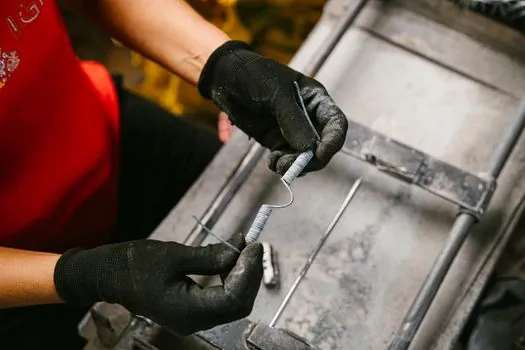
Ring length is set by wrapping the yarn around a mandrel sized to the shaft diameter, marking the butted ends, and cutting on the line, not by measuring with a ruler around the shaft [S2]. A field mandrel can be made from a pipe wrapped with duct tape to the correct OD, which is enough for braided graphite and aramid rings; pre-formed rings from the manufacturer remove that step entirely but require the W and the box depth to be specified correctly at order entry [S2][S4]. Wrong-length rings either leave a gap that the gland cannot close, or bind at the joint and never seat, and both failure modes look identical at first start-up.
The internal-leak encyclopedia entry on gland packing and the cross-reference on cable gland are useful adjacencies when the same engineering team is also sealing cable entries against the same process fluid; the design logic differs but the material-compatibility screening overlaps.
Spec-level background on the components involved: linear guide.