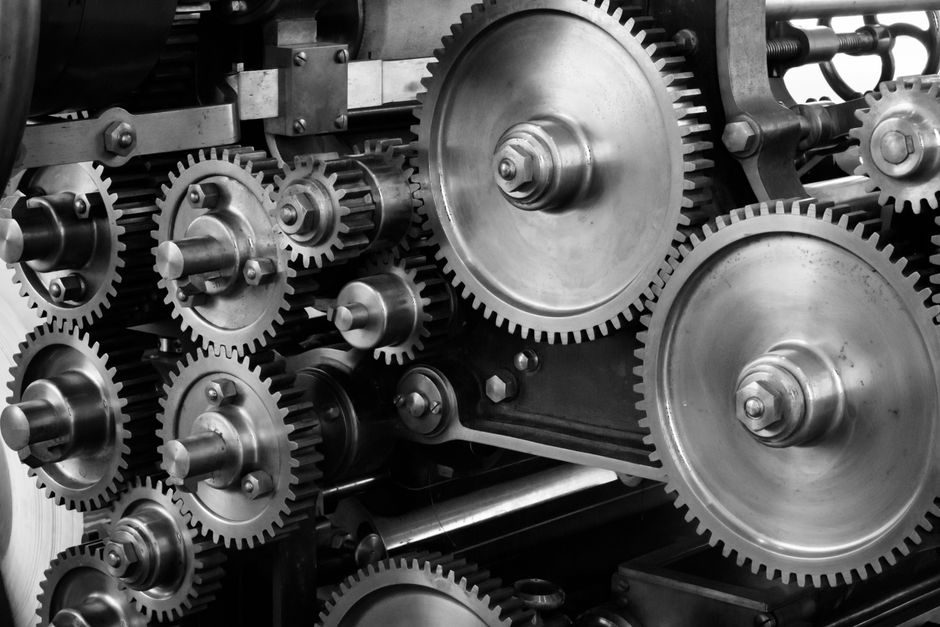
A harmonic drive reducer, also called a strain wave gear, is a zero-backlash, single-stage speed reducer with ratios typically from 30:1 to 160:1, sized for the last axis of six-joint robots, light-load stamping manipulators, and high-precision servo systems [S3].
The unit comprises three parts — wave generator, flexspline, and circular spline — and is specified where high positional accuracy, compact envelope, and high torque density are required over the alternatives of cycloidal reducer or planetary reducer configurations [S1].
Component Geometry and Tooth-Profile Selection
A harmonic drive unit has three concentric elements: the elliptical wave generator (WG), the thin-walled flexspline (FS) with external teeth, and the rigid circular spline (CS) with internal teeth, where teeth mesh at two zones 180° apart, neutralising pitch errors and enabling the characteristic high positional and rotational accuracy [S1][S2].
The double-arc tooth profile enlarges simultaneous meshing tooth count by 20–30% versus the traditional involute profile, giving measurable gains in accuracy, strength, rigidity, and service life; this is the profile currently shipping in OEM catalogues such as the DHDG-14-50-U-R11 short-cylinder hat-type reducer [S3].
Pre-Installation Mechanical Checks
Before mounting, verify the input-end designation on the nameplate — rigid input is standard for model-14 units at reduction ratio 50, with rated output torque of 3.7 N·m at 2000 r/min input, maximum allowable input speed 8500 r/min, and average allowable input speed 3500 r/min — and confirm transmission error is held within ≤90 arc-seconds [S3].
Mating flange runout should be measured against the OEM drawing; the strain-wave mechanism tolerates small radial misalignment on the flexspline but is sensitive to axial preload drift, so a four-point contact pattern check is part of the standard acceptance procedure before any bolts are torqued [S2][S3].
Mounting, Coupling and Torque-Anchor Preload
Bolts securing the reducer housing should be tightened in a star sequence to the OEM-specified value, with the input coupling aligned to within the published concentricity limit; misalignment above the limit is the documented root cause of flexspline fatigue and is not correctable in the field [S3].
For belt- or pinion-driven input configurations, the radial and axial load on the input shaft must stay below the catalog limit — peak starting/stopping torque for a model-14 unit is 12 N·m, instantaneous maximum 23 N·m, average load allowable maximum 4.8 N·m — because harmonic flexsplines are the load-limited element of the assembly and cannot be re-rated in the field [S3].
Lubrication Schedule and Grease Specification
Grease quantity and grade are defined per unit size on the OEM data sheet; underfilled plenums cause hysteresis loss to rise above the published 7.3×10⁻⁴ rad (2.5 arc-min) value, and overfilling drives temperature rise past the low-temperature-rise envelope the design relies on [S1][S3].
Service life is rated at L10: 10,000 h and L50: 50,000 h on current-generation units, provided the average load torque stays within the published envelope and grease is replenished at the catalog interval; exceeding either limit compresses life and the unit should be replaced rather than re-greased in situ [S3].
Electrical Integration with Servo Drives
When paired with a harmonic-drive-class actuator, the drive package accepts CANopen, DeviceNet, EtherCAT and MACRO fieldbuses, with indexing, step/direction, PWM, ±10 V analogue, ASCII serial and discrete I/O as standard command interfaces, which removes the need for a custom motion controller for most robot-axes applications [S6].
Configuration is done through the Harmonic Drive Motion (HDM) PC software, which sets current, position-loop gains and backlash-compensation tables; the starting torque of a model-14 reducer is 6.2 cN·m, so drive tuning should target a torque margin above this floor with the rigid- and spring-constant values T1 = 2.0 N·m, T2 = 6.9 N·m, K1 = 0.29×10⁴ N·m/rad, K2 = 0.37×10⁴ N·m/rad, K3 = 0.47×10⁴ N·m/rad loaded into the controller [S3][S6].
Comparison: Harmonic vs Cycloidal vs Planetary on Decision Criteria
On four decision criteria commonly used for robot-axis selection — single-stage ratio, motion accuracy, fatigue/rigidity, weight — a harmonic drive delivers ratio 30–160, zero-backlash by design, and volume/weight one-third to one-half of a general gear reducer; a cycloidal reducer is heavier but has higher fatigue strength and longer life; a planetary reducer is the baseline for general industrial gearing where the very high single-stage ratio of the strain-wave design is not required [S1].
The split is consistent with current sourcing practice: cycloidal units for high-torque joints (leg, waist, elbow) and large-payload robots; harmonic units for small-load axes and the wrist/hand axes of larger robots; planetary units for general automation where the zero-backlash and ratio-160 envelope is not required and where cost per N·m is the gating metric [S1].
Failure Modes, Acceptance Tests and Escalation
Documented field symptoms map to specific corrective actions: rising hysteresis loss above 2.5 arc-min points to grease depletion or input-bearing wear, not flexspline damage, so re-greasing and bearing replacement restore the unit; tooth-pitch error drift past 1.5 arc-min and rising starting torque above 6.2 cN·m indicate flexspline fatigue and the unit must be replaced because the flexspline is the non-repairable load-limited element [S3].
Acceptance after installation is a measured no-load backlash check at the output shaft, with the target being the catalog value (effectively zero on a properly adjusted unit), and a 30-minute loaded thermal-soak run to confirm temperature rise stays inside the low-temperature-rise envelope; units that fail either test are escalated to the OEM rather than commissioned [S1][S3]. For related robot-axis work, see the cycloidal-reducer installation notes on grease and O-ring selection at RV-E Cycloidal Reducer Installation: Grease, O-Ring, Alignment Specs, and the warehouse-robotics context at Warehouse Robotics 2026: Market Size, Selection Criteria, and Sourcing Map.
For the relevant spec sheets and selection criteria, see harmonic reducer.