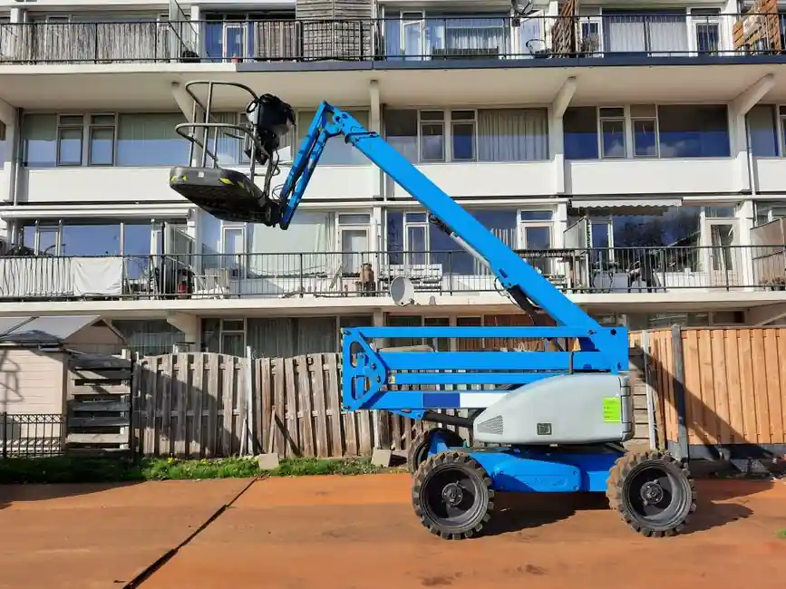
A GEH 90ES heavy-series metric spherical plain bearing measures 90 mm bore by 150 mm OD with a 55 mm width and an 85 mm inner-ring width, and uses a single-fracture outer ring with steel-on-steel sliding contact sized for oscillating boom-pivot duty on excavators and mobile cranes [S8].
Boom pins on hydraulic excavators, telehandlers, and articulated dump trucks see reversing radial load, axial thrust from cylinder stroke, and impact spikes during digging cycles, which is why heavy (E) and extra-heavy (C) series under DIN ISO 12240-1 dominate the pivot specification rather than light-series K [S5][S10]. Compared with standard rolling ball bearings, a spherical plain bearing transmits load through the sliding contact, so it tolerates more contamination and shock at the cost of higher friction and the need for either relubrication or a maintenance-free PTFE liner [S1][S2].
Geometry and Series: Why Heavy (E) for Boom Pins
The DIN ISO 12240-1 dimensional series splits radial spherical plain bearings into light (K), narrow (E), heavy (C in metric, sometimes called E in inch references), and extra-heavy, where the heavier series increase outer-ring width and OD for a given bore to raise static load capacity and allowable misalignment angle α [S5][S10]. A typical E-series bearing with a 90 mm bore lands at 150 mm OD and 55 mm width, while a K-series at the same bore is roughly 130 mm OD and 60 mm width with thinner walls and lower C<sub>r</sub> ratings, so for the same radial load the K unit runs hotter and deforms more at the spherical interface [S8].
For boom pins, the wider outer ring (W<sub>i</sub> larger than standard) is the geometric feature that carries the increased moment from off-axis cylinder force, and single-fracture outer-race construction, pioneered by RBC, lets the ring flex slightly under load to distribute contact pressure rather than concentrating it at the fracture edges [S1][S8]. SKF's radial spherical plain bearing line confirms the same construction rule: sphered convex inner ring mated to a concave outer ring, with the heavy-series OD chosen to fit the expected load and misalignment envelope [S3].
Sliding Contact: Steel/Steel, Steel/Bronze, Steel/PTFE
Three sliding combinations cover nearly every boom-pin spec, and the choice is set by load direction, frequency of relubrication allowed, and contamination exposure: steel-on-steel (hardened and ground, relubricatable) for alternating heavy loads and shock, steel-on-bronze for medium sliding speeds with regular grease, and steel-on-PTFE fabric (maintenance-free) for one-directional load and small-to-medium impact [S5][S6]. Steel-on-steel is the default for high-shock booms because both rings can be case-hardened to roughly 55-62 HRC, taking surface contact pressure that would brinell a through-hardened lower-Rc race [S1][S4].
For shock specifically, LDK and BSA both call out case-hardened high-quality bearing steels as the dedicated material choice, with the outer race often through-hardened and the inner race case-carburized to combine a tough core with a hard, wear-resistant surface [S4][S6]. THK's SB and SA1 lines follow the same logic, using high-carbon chromium bearing steel for both rings in heavy-load self-aligning service, while FLURO builds to DIN ISO 12240-1 with both relubricatable and maintenance-free options across the same dimension table [S9][S10]. When the equipment duty cycle allows relubrication every 250-500 hours, steel-on-steel is hard to beat on PV (pressure times velocity) limit; when the pin is buried inside a boom and grease access is poor, a PTFE-liner unit is the pragmatic call [S2][S5].
Misalignment, Tilt Angle, and Edge Loading
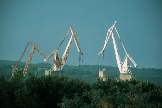
Misalignment angle α, the static tilt the bearing can hold between inner and outer ring, is the spec number that often decides whether a heavy-series part is needed at all: a K-series unit is typically rated near ±6° to ±10° of tilt, while heavy E/C series extend that envelope to roughly ±10° to ±17° depending on bore and series [S3][S5]. On a boom pin this tilt is not optional, it is the geometric sum of cylinder stroke, pin deflection under load, and assembly stack-up, and exceeding the rated α drives the contact ellipse toward the edge of the spherical race, accelerating liner wear and brinelling the race [S2][S3].
Three engineering controls are used in practice: select a series whose α rating exceeds the calculated maximum tilt by at least 20-30%, machine the clevis ears parallel within 0.1 mm to keep the pin from binding, and use spacers or shims to center the housing so the spherical contact sits at the equator of the inner ball, not at its pole [S2]. After any surface coating on the pin or race, bore and pin diameter, sphericity, and breakaway torque must be re-measured, because a 5-10 µm coating shifts preload and can close the running clearance that the rated α depends on [S2].
Shock Loading, Case Hardening, and Sealing
High-shock boom-pivot duty pushes spherical plain bearings into a regime where impact energy is absorbed by elastic deflection of the outer ring plus the case-hardened surface of the inner ring, and RBC's ImpactTuff line is a publicly documented case-carburized construction aimed at exactly this duty [S1]. BSA's guidance on high-shock applications aligns: specify case-hardened high-quality bearing steels, verify that the sliding surface hardness is in the upper 50s HRC minimum, and pair the bearing with hardened pins of compatible hardness to prevent adhesive transfer [S6]. The single-fracture outer ring is the structural feature that lets the race absorb shock without crack propagation, and it remains the dominant heavy-series construction for mobile-equipment pivots [S1][S8].
Sealing is the second half of shock survival: a spherical plain bearing on a boom pin is routinely exposed to dust, mud, and water jets, and unprotected races will corrode and brinell within a few thousand hours in those conditions [S2][S7]. Hardened boots, nitrile or polyurethane wipers on the pin, and grease-purgeable labyrinth seals are the standard stack, with H1 food-grade grease used where the equipment operates near edible-cargo handling or where washdown chemistry is aggressive [S2]. For comparison, the same contamination control logic shows up in any shock absorber spec on a mobile machine: seal integrity dominates service life once the geometry and material are correct.
Sizing, Standards, and Selection Criteria Compared
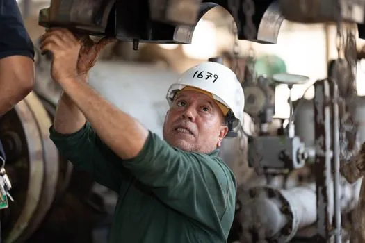
Sizing a heavy-series spherical plain bearing for a boom pin reduces to four numbers: bore (set by pin diameter, typically h6-h9 fit), OD (set by clevis geometry and the series table in DIN ISO 12240-1), width (set by the moment arm and the required α), and static C<sub>0r</sub> rating (set by the peak radial load including shock factor) [S2][S5][S10]. Three practical criteria separate the candidate options: (1) sliding combination, steel-on-steel for the highest PV and shock, steel-on-PTFE for maintenance-free but lower PV, steel-on-bronze for slow oscillatory service; (2) sealing and relubrication access, which forces the steel-on-PTFE choice when grease is hard to reach; (3) misalignment angle, where heavy E/C series give roughly 1.5-2.5× the α of light K series at the same bore [S3][S5][S8].
The standards anchor is DIN ISO 12240-1, which defines dimensional series, tolerances, and radial internal clearance, while load ratings and life calculations remain manufacturer-specific and are not standardized, so direct cross-vendor substitution requires checking C<sub>r</sub>, C<sub>0r</sub>, α, and PV against the application [S5][S10]. For deeper construction trade-offs between formed and machined outer races used in these heavy series, the practical decision map is laid out in formed vs machined radial spherical plain bearings, and for the load-capacity question that often sits beside bearing selection, the full complement vs caged roller bearing trade-off is a useful adjacent read.
Common Failure Modes on Boom Pins
Three failure modes dominate field reports on heavy-series spherical plain bearings in boom service: (1) brinelling and race deformation from shock loads that exceed the static C<sub>0r</sub>, (2) abrasive wear and edge loading from running past the rated misalignment angle, and (3) corrosion-driven spalling from water and chloride ingress past damaged seals [S2][S6]. The diagnostic pattern is consistent: rising breakaway torque, radial play above roughly 0.5-1.0% of bore, and brown-red staining around the seal lip are the early signs, while flaked PTFE liner material or metallic debris in the grease confirms an advanced stage that calls for replacement rather than re-lubrication [S2][S7].
Forensic discipline matters: confirm the seal and boot before condemning the bearing, because a torn wiper will destroy a healthy race in a few hundred hours, and conversely re-measure α and PV after any field repair to make sure the replacement unit is not just newer but correctly specified for the same duty [S2][S7]. When the equipment is a mobile crane or excavator with documented cycle counts, track grease sample ferrous-particle content between services, since spherical plain bearings do not give a clean acoustic warning the way rolling-element ceramic bearing variants might in less shock-loaded service.
Trackable signals for the next 3-6 months: any vendor update to ISO 12240-1 dimensional tolerances for E and C series, expanded ImpactTuff-style case-carburized heavy-series offerings from RBC competitors in the same bore range, and clearer published PV limits for steel-on-PTFE heavy-series units at the 80-150 mm bore range used on 20-40 tonne excavator booms.