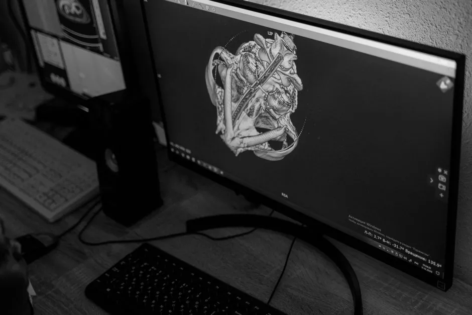
A flat panel detector (FPD) converts X-rays into a digital image by absorbing photons in a conversion layer, generating proportional electrical charge, and reading that charge with a thin-film transistor (TFT) array typically laid out at 1024 x 1024 pixels or higher [S4][S6].
Two architectures coexist: indirect, where a scintillator first turns X-rays into visible light before a photodiode/TFT stage turns that light into charge, and direct, where a photoconductor such as amorphous selenium (a-Se) generates electron-hole pairs in a single step [S1][S3][S4]. The detector's role inside the imaging chain is well established in digital radiography, fluoroscopy, interventional radiology, and industrial non-destructive testing, replacing both film/screen cassettes and older image-intensifier (II/TV) chains [S1][S9].
Detector Architecture: Four Functional Layers
Every FPD, whether direct or indirect, stacks the same four functional blocks: a conversion layer, a TFT pixel array, a readout integrated circuit (ROIC) with gate drivers and analog-to-digital converters, and a protective housing that also provides electromagnetic shielding [S2]. The conversion layer sits on top and is the first point of contact for incoming X-ray photons, while the TFT array beneath it holds millions of pixel capacitors that store charge proportional to the X-ray energy absorbed at each site [S2].
The TFT array itself is fabricated on amorphous silicon in most medical FPDs, with each pixel acting as a tiny switch that is scanned row by row during readout [S3][S5]. Supporting electronics, including gate drivers, data lines, and ADCs, are tightly integrated to minimize noise and preserve signal fidelity, and the housing shields the assembly from RF interference in clinical and industrial environments [S2].
Indirect Conversion: Scintillator plus Photodiode/TFT
Indirect FPDs use a scintillator as the first stage, typically cesium iodide (CsI) or gadolinium oxysulfide (Gd2O2S, also called GOS or GadOx), followed by an amorphous silicon photodiode matrix and a TFT readout [S3][S4][S7]. X-ray photons are absorbed in the scintillator and re-emitted as visible light photons, which then strike the photodiode layer and liberate charge proportional to the original X-ray energy [S3][S7].
CsI is usually grown as a columnar needle structure that channels the visible light straight down toward the photodiode, limiting lateral spread and preserving spatial resolution; GOS is a powder phosphor that emits more diffuse light, costs less, but produces more blur [S2][S4]. Indirect systems are widely used for general radiography, fluoroscopy, and angiography, where the dose-saving benefit of higher detective quantum efficiency (DQE) at lower exposures is valued [S1][S5].
Direct Conversion: Photoconductor and TFT

Direct FPDs skip the light step and convert X-rays into electron-hole pairs inside a photoconductor, most commonly amorphous selenium (a-Se), with cadmium telluride (CdTe) used in some higher-energy or industrial variants [S3][S4][S5]. A bias voltage applied across the photoconductor layer sweeps the liberated charge directly to the TFT array below, where it is read out as a digital signal [S2][S3].
Because there is no intermediate visible-light stage, direct detectors tend to show less lateral signal spread and therefore deliver sharper spatial resolution, which is why they are the preferred choice for mammography and other high-detail applications [S2][S4][S5]. The trade-off is that the photoconductor and high-voltage bias electrode add complexity and the conversion gain is generally lower per absorbed X-ray than a CsI scintillator, so DQE behavior differs from indirect designs [S1][S2].
Direct vs Indirect: Decision Criteria Compared
The right architecture depends on the priority stack of the application, and the trade-off is consistent across medical and industrial users [S1][S2][S4]. For general radiography and fluoroscopy where dose efficiency matters most, indirect CsI or GOS panels dominate, and within that family CsI wins on resolution while GOS wins on cost [S4][S5].
For mammography and high-detail static imaging, direct a-Se panels are specified because the absence of a light-conversion stage preserves microcalcification visibility [S2][S5]. For interventional fluoroscopy, indirect panels remain standard because of higher DQE at low dose and the field-uniformity benefits of TFT readout versus the older image-intensifier/TV chain [S1].
Signal Readout and Image Formation
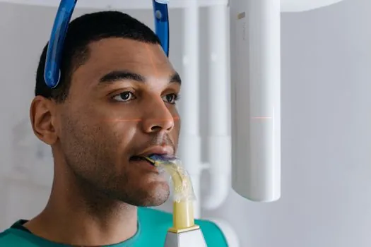
Once charge is stored on each pixel capacitor, the TFT array is scanned row by row, the analog charge is digitized by on-board ADCs, and the resulting digital frame is handed to image-processing software for flat-field correction, gain calibration, and defect-pixel mapping [S2][S6]. The TFT acts as a switch that connects each pixel to its column readout line, so any given pixel is read only when its row is selected, which allows the panel to expose the next frame while the current one is read out [S5][S6].
Modern FPDs are described as large-area X-ray detectors because they integrate the X-ray-sensitive layer directly over the TFT array, typically on a single amorphous-silicon substrate, and the pixel pitch now commonly supports diagnostic-resolution images with millions of effective elements [S6]. This monolithic integration, combined with real-time readout, is what allows FPDs to deliver the instant digital imaging workflow that has displaced film/screen and computed radiography in most clinical and many industrial inspection cells [S5][S9].
Failure Modes, Limits, and Standards Anchors
Common FPD failure modes include residual signal lag from previous exposures, image artifacts from defective TFT pixels, and veiling glare in lower-exposure fluoroscopy, all of which were flagged as residual issues even as FPDs otherwise displaced image intensifiers [S1]. Direct detectors are also sensitive to charge recombination if the bias field is not uniform, so high-voltage electrode integrity is a design-critical concern [S3].
Image quality is conventionally benchmarked against detective quantum efficiency (DQE), modulation transfer function (MTF), and the ALARA dose principle, with the pediatric-fluoroscopy literature noting that first-generation FPDs lacked some image quality at the lowest fluoroscopic exposures compared with mature II/TV chains but offered better DQE overall and no geometric distortion [S1]. For engineers sourcing panels, the practical selector variables are pixel pitch, scintillator material (CsI vs GOS) for indirect, photoconductor (a-Se vs CdTe) for direct, maximum frame rate, and warranty terms, with industrial X-ray inspection systems drawing on the same panel families used in medical DR [S4][S6].
Engineers building inspection stations around these detectors will also see familiar industrial signal-chain components, such as the digital multimeter used to verify bias-supply rails, or the digital panel meter in older analog readout stacks, and the broader industrial X-ray ecosystem shares a fair amount of physics, scintillator chemistry, and shielding logic with medical FPDs. Trackable signals to watch next: pixel pitch continuing to drop below 100 micrometers for mammography-class direct panels, and wider adoption of CdTe for high-energy industrial and security screening where a-Se thickness becomes impractical.
Background reading: How a Dial Indicator Converts Plunger Travel into a Needle Reading: Mechanism.