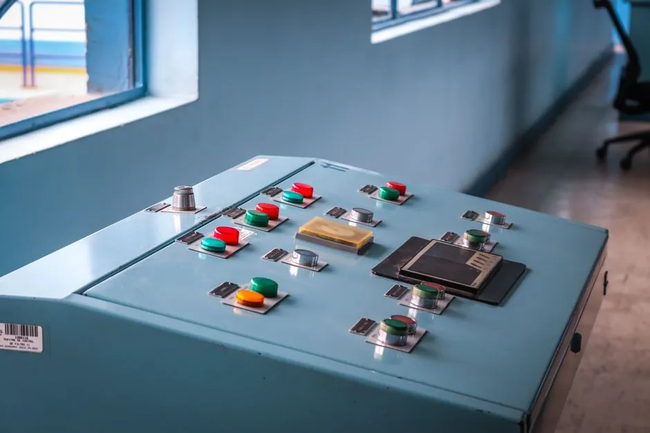
Most medium-voltage switchgear panels require 6 to 12 temperature sensors per cubicle to cover every bolted joint, breaker contact pair, cable termination, and CT termination, with a single-phase, three-joint minimum at the busbar and additional points at the breaker primary disconnects and outgoing cable terminations [S3][S5].
Sensor count scales with the number of series-connected electrical interfaces inside the panel, not with the panel's physical size, so a 12 kV single-bus, single-breaker cubicle typically lands at 8 to 10 points while a 36 kV GIS bay with three breaker positions often runs 20 to 30 fiber-optic measurement points [S3][S6].
Where Heat Actually Builds in a Switchgear Cubicle
Hot spots concentrate at the bolted copper-to-copper or copper-to-aluminum interfaces: busbar splices, breaker tulip contacts, cable lugs, CT secondary terminal blocks, and withdrawable-breaker primary disconnects are the five classes of joint that drive 90% of thermal failures in metal-clad gear [S1][S4].
A medium-voltage (1–36 kV) breaker cubicle contains roughly 4 to 6 critical bolted joints per phase: incoming busbar splice, upper primary disconnect, lower primary disconnect, breaker main contact, CT primary stud, and the cable termination lug, so a three-phase panel realistically demands 12 to 18 measurement points if every joint is monitored, dropping to 6 to 10 when only the highest-risk joints are instrumented [S3][S5].
For low-voltage (under 1 kV) switchboards, the bolt count and the current density both rise, so a 1600 A frame section typically needs 9 to 12 sensors, with 30 to 50 sensor configurations common across a full motor control center lineup [S4].
Three Sensor Technologies Compared for Switchgear Duty
Fiber-optic fluorescent and GaAs sensors, battery-powered wireless surface-mount transmitters, and infrared thermal cameras are the three dominant approaches; each maps differently to the IEEE C37.20.3 dielectric test requirement, to explosion-risk zones, and to retrofit vs greenfield installations [S3][S4].
Fiber-optic probes are the only option safe to mount directly on a live conductor in HV switchgear because they carry no metallic conductor into the field, and they hold ±1°C accuracy at 100°C, but they require a dedicated temperature transmitter per probe and per-channel routing through a temperature monitor [S4][S6].
Wireless surface-mount sensors (433 MHz or 2.4 GHz, battery life typically 8 to 12 years at 30 s sample interval) are the lowest-cost retrofit option, install in minutes per point, and are widely used on MV cable terminations and breaker contacts up to 36 kV, but the metal enclosure can attenuate the radio link and a single gateway normally handles 40 to 80 sensors per panel lineup [S2][S3].
Infrared cameras deliver a 2D heat map and a visual record for inspection rounds but are non-contact and cannot be aligned to a bolted joint reliably, so they are a periodic walk-down tool, not a continuous online temperature recorder [S3][S4].
Selection Criteria That Drive Sensor Count
Selection for MV switchgear service converges on six engineering criteria: dielectric withstand per IEEE C37.20.3, response time short enough for operator action, sensor lifetime matching the switchgear's 30-year design life, calibration stability, and ability to mount on a 24 kV energized conductor without changing the panel's field profile [S4][S5].
Continuous monitoring detects 70% more developing faults than thermochromic indicators or periodic IR inspection alone, which is the strongest single argument for moving from 2 to 3 spot sensors to a full 8 to 12 point coverage on each cubicle [S2].
For arc-flash or gas-insulated compartments where the user wants continuous hot-spot data without the dielectric risk of routing metal wires, fiber-optic fluorescent probes are the only credible direct-measurement option, with typical temperature measurement accuracy of ±1°C and response times below 1 s [S4][S6].
Who This Sensor Count Is For, and Who Should Not Bother
Full per-joint instrumentation makes sense for MV and HV switchgear feeding critical or unrepairable loads (utility incomers, hospital isolators, data-center UPS feeders, offshore platform ESVs), and for any cubicle above 1250 A where bolted-joint resistance drift is the dominant failure mode [S1][S3].
Small commercial distribution boards, light-duty 400 V motor starters, and rarely-loaded capacitor banks generally do not justify 8+ sensors per panel; 2 to 4 wireless sensors at the main lugs and the highest-loaded breaker terminations are usually the right ceiling, and over-instrumenting costs more in batteries and gateways than it saves in fault prevention [S2][S5].
The same point count calculus does not apply to thermal mapping of controlled environments such as pharmaceutical chambers, where 15 to 16 sensors per 20 m³ is the established practice for chamber validation, a very different use case from switchgear joint monitoring [S7].
Standards, Installation Rules, and Sourcing Signals
IEEE C37.20.3 governs the dielectric and mechanical tests that any temperature sensor must survive if it is to be retrofitted inside a metal-clad switchgear panel, and it is the single standard most procurement specs reference on this topic [S4].
Continuous thermal monitoring of MV switchgear joints and busbar connections has been a shipping capability in major OEM portfolios for several years, with publicly documented product lines covering fluorescent fiber-optic, wireless, and IR technologies from ABB, Eaton, and Osensa, which is a useful cross-check on technology maturity when the spec is written [S1][S6][S9].
Trackable next signals: a per-cubicle sensor-count clause in new utility and data-center switchgear specs landing in late 2026 procurement, and the publication of any revision to IEEE C37.20.3 that changes retrofit-sensor dielectric tests.
For related coverage, see AC Torque Motor Output Torque vs. Supply Voltage: How Adjustment Actually Works.