On an AC torque motor, output torque tracks the RMS supply voltage applied to the stator: raise the voltage, current rises, and torque rises in proportion; lower the voltage, current falls, and torque falls, all while the motor holds any speed from full running down to a stalled condition without tripping on thermal limits [S1][S3].
Because the device is purpose-built around that behaviour, it is the de facto choice for winding, unwinding, and web-tension duty where the load wants constant tension rather than constant speed, and the operator simply dials supply voltage to set the torque setpoint [S1][S3]. For a fuller look at how torque itself is defined and calculated, see the AC motor fundamentals entry.
Why voltage is the torque knob: the V–I–T chain
Torque in any rotating machine is flux times in-phase current, and in an AC induction machine the flux is set by the ratio of applied voltage to supply frequency, so dropping the voltage at fixed frequency drops the flux, drops the current, and drops the torque together [S5]. The net behaviour at the shaft is: more voltage equals more torque, and the proportionality is close enough for sizing work provided the motor stays inside its thermal envelope [S2][S4].
A practical consequence is that for a torque motor locked at zero speed, the controller only has to vary RMS voltage, not frequency, to move the output along the steep, sloping torque-speed curve that defines the family [S1][S3]. That curve is what differentiates a torque motor from a general induction motor: standard induction motors try to hold speed as load varies, while a torque motor lets speed droop on purpose so the same motor can sit stalled at a controlled tension [S3].
Three hardware ways to vary the voltage
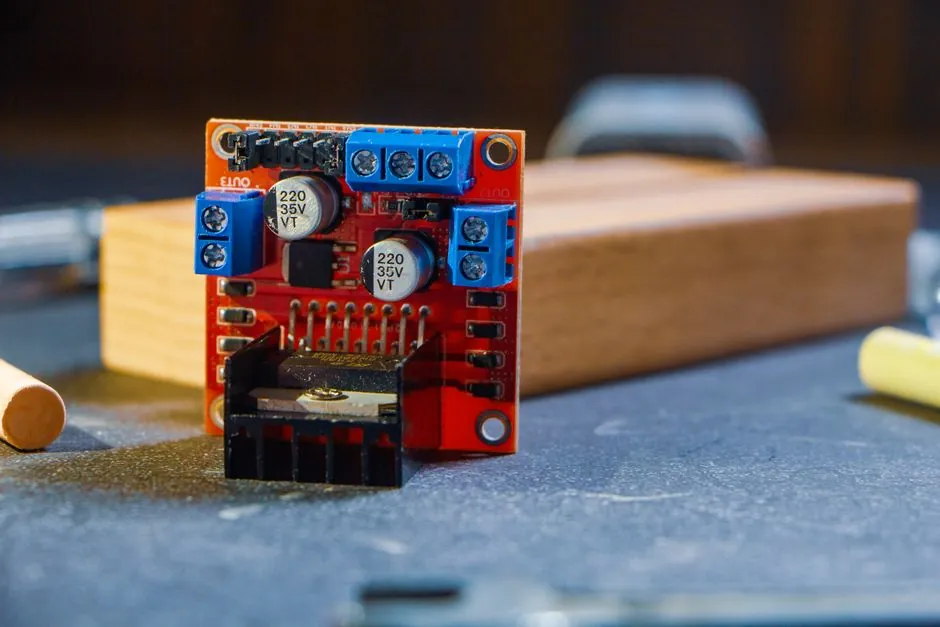
Operators have three common options to reduce the AC supply reaching the motor terminals, and the choice drives cost, resolution, and harmonic content [S7]. The first is an autotransformer (variable transformer) feeding the motor directly: simple, rugged, no electronics, and a clean sine wave at the output, which is why it is still specified for low-duty film and foil lines.
The second is a thyristor (SCR) phase-angle controller that chops each half-cycle to lower the RMS level; this is the cheapest stepless method but introduces notching and harmonic current that can upset sensitive drives and PLC analog inputs on the same bus [S7]. The third, used on the SESAME built-in regulator type and similar Bodine-style designs, is a resistance-controlled regulator packaged inside the motor's terminal box, where an external potentiometer sets the firing point and the motor's torque follows [S3]. For drives-style applications where a VFD is already present, the same torque motor can be fed from a variable frequency drive running in V/Hz mode, since V/Hz is essentially a voltage-based torque command at low slip.
Locked-rotor operation: where torque motors earn their keep
A torque motor is wound and cooled so it can sit at zero speed (locked rotor) and still dissipate I²R losses at rated current, which is what lets it hold tension on a stopped reel without burning up in minutes [S1][S3]. Oriental Motor's product literature is explicit that the output torque becomes very limited in continuous locked-rotor operation, which is why datasheets publish separate ratings for stall torque vs. short-duty running torque [S1].
The practical rule when reading a torque motor curve is: the curve at any applied voltage gives torque as a function of speed, and the stall (zero speed) point on that curve is the available holding torque at that voltage. So halving the voltage to the terminals roughly halves the available holding torque, with the caveat that rotor temperature and slip-dependent rotor resistance shifts make the relationship non-linear at the extremes [S3][S4]. For sizing workflows that step from this V-T behaviour into inertia matching and speed-curve plotting, the stepper motor sizing workflow covers the same arithmetic on a different motor family.
Selection criteria: voltage-controlled vs. closed-loop alternatives
The right comparison is voltage-controlled torque motor against a torque sensor-closed servo or a vector VFD, not against another induction motor. The torque motor wins on price, simplicity, and ability to hold torque at zero speed without encoder feedback, but loses on bandwidth, dynamic stiffness, and accuracy: there is no closed loop trimming the actual shaft tension to a setpoint, so a dancer or load cell is often added externally. [S3]
For web handling where tension tolerance is loose (±5-10%) and reels are small, a voltage-controlled torque motor fed from an autotransformer is the lowest-cost solution. For high-speed slitting, extruder film casting, or wire drawing where tension must stay within 1-2% as the reel builds from 100 mm to 1000 mm diameter, a vector drive with shaft torque feedback is the better fit despite the extra cost [S3]. Engineers who already spec a medium-voltage VFD on the line will find that the drive's torque-mode output removes the need for a separate regulator entirely.
Limits, failure modes, and the standards that bracket them
Reducing voltage lowers torque and lowers heat at the same time, which sounds free, but the ceiling is set by the motor's thermal class and the rotor's ability to dissipate locked-rotor losses for the duty cycle you actually run [S1][S3]. The common failure pattern is not "voltage too low" but "voltage set to deliver rated torque at locked rotor for longer than the insulation class allows," which manifests as stator winding resistance drift and eventual turn-to-turn short. The general induction-motor safety and test references (NEMA MG-1, IEC 60034-1 for rating and performance, IEC 60034-11 for thermal protection) apply to torque motors the same as to standard induction machines.
When the torque motor is driving a hazardous-area winder, the wiring side of the installation falls under the usual IEC 60079 series for explosive atmospheres, and the cable entries and motor terminal box must be specified to match the zone. Field practice for verifying the supporting components is covered in the ATEX cable gland certificate check, which matters because a torque motor's locked-rotor current is essentially the same as its rated current, so gland and conductor sizing must be done at full-load amps, not at an averaged running value.
Bench verification: measuring the V-T curve before commissioning
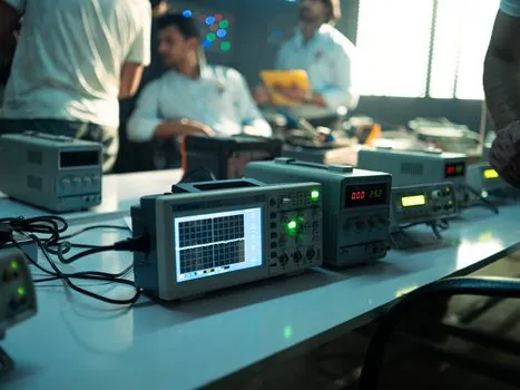
Before putting a torque motor on a winder, the prudent step is to map voltage in versus torque out at zero speed on a bench stand using a hydraulic test actuator or a reaction torque transducer, then compare against the published curve. The bench fixture, the load cell calibration, and the dwell time at each voltage point together determine whether the curve you trust in production is the one the vendor printed or the one your motor actually delivers [S7].
A reproducible bench rig for that kind of torque verification is laid out in the hydraulic test actuator setup guide, which pairs with a torque motor's V-T test by giving a known reaction load while you sweep the supply voltage from 50% to 110% of nameplate. Trackable signal for the next 6 months: more torque-motor SKUs shipping with integrated electronic (IGBT-based) regulators instead of the legacy potentiometer-input SCR box, as drive manufacturers consolidate tension-control hardware into the same VFD platform that already handles VFD speed loops on the same machine.