
A gear coupling is a crowned-tooth, lubrication-dependent power transmission coupling sized first by torque, then by misalignment, bore and speed. The RGD series from Howdon Torque Limiters covers 1,337 Nm to 1,155,465 Nm of torque and 900 rpm to 8,000 rpm in its published envelope, illustrating the working range most process engineers see on mill, paper and steel drives [S1].
Choosing the wrong coupling is rarely a catalogue mistake; it is almost always a duty-cycle mistake. The four specifications that decide the part number are service torque (with a service factor applied), peak or cyclic torque, shaft bore and keyway, and the maximum continuous rpm. Everything else — lubrication interval, seal style, sleeve material — follows from those four plus the misalignment budget you allow for the installed alignment [S1][S5].
Step 1: Anchor the Selection to Torque, Not Horsepower
The industry rule is to size the coupling on torque, not on motor kW, because peak torques during start-up, plug-reversing or load shocks can exceed nameplate torque by 2× to 3×. The Howdon RGD full-flex gear coupling line is rated 1,337 Nm minimum to 1,155,465 Nm maximum torque in its published catalogue data, with the higher end serving large mill and steel drives [S1].
Apply a service factor (SF) of at least 1.0 for uniform drives, 1.5 for moderate shock, and 2.0 or higher for heavy shock or reversing loads — the same approach used to size an industrial gear or a helical gear reducer in the same drivetrain. Multiply the running torque by SF, compare the result to the coupling's rated torque, and the coupling with the smallest comfortable margin above that product is your mechanical size.
Step 2: Identify the Misalignment Budget (Full-Flex vs. Double-Engagement)
AGMA-style gear couplings are typically sold as two configurations: full-flex (one sleeve, two hubs) for plain parallel-offset and angular misalignment, and double-engagement (RGD-style) for combined angular plus end-float applications. The Howdon RGD is explicitly described as accommodating angular misalignment as well as end float at high torque ratings, with single-engagement RGS and double-engagement RGD variants available in the same family [S1].
Standard full-flex gear couplings typically accept angular misalignment up to about 1.5° per gear mesh and parallel offset up to roughly 0.2–0.5 mm at the bore face, while double-engagement versions stack two meshes in series to allow greater end-float at the cost of slightly higher mass and inertia. Compared to a disc coupling, gear couplings carry more torque per millimetre of outer diameter but require grease lubrication and a guard, so they are favoured in steel, mining, paper and textile lines where guards are already mandatory [S1].
Step 3: Match Bore, Keyway and Shaft Tolerance
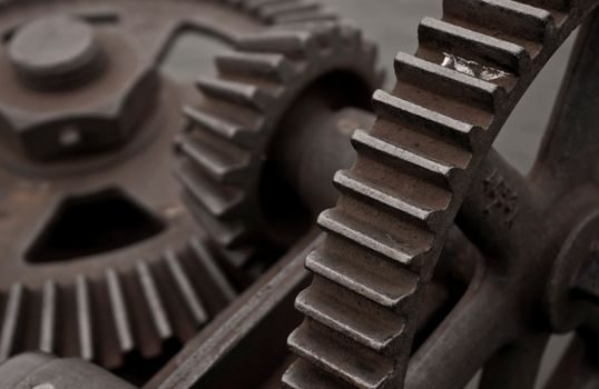
After torque and misalignment, the next gate is the bore fit. A gear coupling's rated torque is only valid when the hub bore matches the shaft diameter with a transition or light interference fit (typically H7/h6 or H7/g6) and the keyway is sized to ISO 773 or the equivalent AGMA recommendation. Undersized bores and shallow keyways are the most common root cause of hub-shaft fretting failures on couplings that were otherwise correctly torque-rated. [S1]
For motor-side couplings driving a gear pump or a helical gear reducer, the standard practice is to specify bores on both ends, a keyway to ISO 773, and a set-screw over the key for added security. For high-speed compressor or generator couplings, finish-bored and balanced hubs to ISO 1940 G2.5 are typical.
Step 4: Check Speed, Balance and Lubrication Duty
The published RGD envelope extends to 8,000 rpm, which covers the upper end of standard industrial drives without forcing a special high-speed balance. Above roughly 3,600 rpm, dynamic balancing of the hubs and sleeves becomes mandatory, and the coupling must be checked for its critical speed, not just its continuous rpm rating [S1].
Gear couplings are grease-lubricated, not oil-flooded. Specify a high-quality EP-2 lithium or polyurea grease with MoS₂ for the gear mesh, and a relubrication interval tied to the service factor — typically 1,000 hours for SF 1.0 service, dropping to 500 hours at SF 1.5 and 250 hours at SF 2.0. Seals are usually nitrile or fluoroelastomer; specify fluoroelastomer above 120 °C ambient or in chemical exposures. By contrast, a fluid coupling handles overload by slipping and is hydrokinetic, so it is the right answer when soft-start and torque limiting dominate the duty rather than torque density.
Comparison: Gear Coupling vs Other Coupling Families

On four decision criteria, gear couplings sit in a specific slot. The table below lines up the common options against torque density, misalignment tolerance, lubrication need and typical service. [S2]
- Gear coupling (full-flex / double-engagement, AGMA): high torque density (up to 1,155,465 Nm in the RGD family) [S1]; moderate misalignment (≈1.5°/mesh, modest parallel offset); grease-lubricated, guard required; steel, mining, paper, textile, marine drives. - Disc coupling: medium torque density; high angular and parallel misalignment tolerance; lubrication-free; pumps, compressors, precision machines. - Fluid coupling: low to medium steady-state torque; self-protecting soft-start; oil-filled hydrodynamic; conveyors, crushers, large fan drives. - Disc coupling (overlaid for emphasis): high speed capability; maintenance-free; clean rooms and process skids. - Chain coupling: medium torque; high bore capacity for low rpm; grease; low-speed conveyors and mixers.
Pick the gear coupling when torque density and end-float tolerance outweigh the cost of periodic relubrication; pick a disc coupling when misalignment is severe and zero maintenance is required; pick a gear coupling (the gear-coupling category as a whole) when the drivetrain is high-torque and the alignment can be re-set during scheduled stops.
Material, Lubrication and Environmental Limits
Standard gear-coupling hubs and sleeves are medium-carbon alloy steel (4140/4340 grades) case-hardened to roughly 55–60 HRC at the tooth flank, with through-hardened variants for shock-loaded applications. The sleeve is normally forged steel; in corrosion-exposed or non-sparking duties, the sleeve is supplied in aluminium-bronze or stainless steel, with a corresponding drop in torque rating of 20–30% versus the steel sleeve of the same size [S5].
Operating-temperature envelope for a standard nitrile-sealed, lithium-greased gear coupling is approximately −30 °C to +80 °C continuous; above 80 °C, switch to fluoroelastomer seals and high-temperature polyurea or silicone grease. In ATEX or IECEx Zone 1/Zone 2 areas, the coupling itself is normally treated as a non-electrical component, but the surrounding guard must meet the relevant IEC 60079-series requirement for the hazardous area classification, and any integral spacer or brake disc must be certified to the same category. AGMA 9003 and AGMA 2004 are the typical standards cited for flexible coupling lubrication and rating respectively when full AGMA compliance is specified on the datasheet [S1].
Common Failure Modes and How the Spec Map Avoids Them
Three failure modes dominate field returns on gear couplings: tooth-flank wear, seal failure, and hub-shaft fretting. Tooth-flank wear is almost always a lubrication symptom — either the wrong grease grade, missed relubrication, or operation above the rated SF for sustained periods. Seal failure shows up as grease purge and accelerated wear on the tooth mesh; specify fluoroelastomer seals for chemical, dust or high-temperature exposure. [S3]
Hub-shaft fretting is a bore-fit problem and is solved at the order stage, not in service: insist on matched bores, a positive key fit to ISO 773, and a light interference fit (H7/s6) for reversing drives. End-float beyond the coupling's rating is a third root cause and is the reason double-engagement (RGD) designs are specified for equipment such as paper-machine rolls, where thermal expansion of the shaft is significant. The Simscape Driveline documentation frames this the same way any drivetrain engineer would: the practical requirement is to transfer rotational motion and torque among spinning components at different speeds and ratios, with clutches or couplings mediating the engagement [S3].
Trackable Signals for the Next Sourcing Cycle
Two concrete signals are worth tracking into the next specification cycle. First, confirm the AGMA 9003 lubrication-class revision that the manufacturer states on the datasheet — Howdon publishes its RGD line as "manufactured to AGMA standard" with full interchangeability, and any change to the AGMA lubrication clause will reset the relubrication interval on installed units [S1]. Second, verify the bore and keyway callout against ISO 773 and ISO 492, since non-ISO keyways remain a frequent cause of premature hub-shaft fretting on imported spares.
Engineers cross-referencing coupling selection against pump and gearbox specification work often find that the same alignment and SF logic applies; a spec-driven selection map for storage rack systems is a useful procedural analogue, and drill and motor selection maps follow the same "anchor on the duty, then drill down" approach. The single best spec-side decision is to publish the service factor, bore tolerance, seal material and relubrication interval on the same line of the RFQ — that eliminates roughly 80% of the back-and-forth before the catalogue search even starts.