
Selection of a hydraulic actuator starts with four binding constraints: available supply pressure (typically 160–350 bar for industrial hydraulics, lower for mobile and subsea duty), required force or torque, stroke length or rotation angle, and the position-control bandwidth the machine needs.
The actuator is one element of a stack — pump, hydraulic power unit, hydraulic valve, and hydraulic cylinder or motor — and the cheapest place to get the spec wrong is at the interface between them. Treat the actuator, the directional control valve, and the power unit as a single sourcing decision rather than three independent ones.
Step 1: Match the Actuator Family to the Mechanical Job
Linear work (push, pull, clamp, lift) almost always points to a hydraulic cylinder; rotary work (swing, indexing, indexing a valve, rotating a friction clutch) points to a hydraulic actuator of the rack-and-pinion, vane, or helical type. The MathWorks rotating-actuator reference example [S3] shows a Rotating Single-Acting Actuator (IL) block sized for a 4.5 l/min pump and a 10 bar relief valve, with stroke cycles run at 120 rad/s and 275 rad/s to expose how centrifugal fluid force adds to static pressure force at higher shaft speeds [S3].
For pure linear reciprocation with position feedback, the same vendor's analog position controller example [S1] models a 0–5 V reference command that drives 0–100 mm of ram displacement through a torque-motor-driven spool valve and a proportional-plus-integral op-amp controller — a useful reference for sizing a 100 mm stroke, sub-1 kHz closed-loop servo [S1]. Where the duty is heavy and continuous — press lines, marine steering, large dam gates — double-acting cylinders with through-rods and wear bands dominate; for clamping or simple ejector duty, single-acting spring-return designs remove one port, one hose, and one failure mode.
Step 2: Translate Load into Pressure × Area × Duty Cycle
Force from a cylinder is F = P × A × η_m, where A is the effective piston area, P is the working pressure, and η_m is the mechanical efficiency (typically 0.85–0.95 for a packed industrial cylinder, lower for small-bore mobile units). For a 100 mm bore at 200 bar, the theoretical push force is roughly 157 kN; with a 70 mm rod on the retract side, retract force drops to about 80 kN — the asymmetry matters any time the load is not gravity-balanced. [S3]
Duty cycle drives thermal sizing of the power unit, not the actuator itself, but it is a frequent misspecification: continuous duty above ~60% of rated flow without a heat exchanger collapses oil viscosity and degrades seal life. Industrial presses, injection molding clamps, and mill stand cylinders are continuous-duty; mobile boom lift and tractor steering are intermittent. Quote the duty in seconds-on/seconds-off and the strokes-per-minute; let the power-unit supplier size cooling, not the actuator supplier.
Step 3: Choose the Control Tier — On/Off, Proportional, or Servo

Three tiers separate cleanly in cost and in performance. On/off directional valves with limit-switch end-of-stroke feedback handle 80% of industrial clamp, gate, and ejector work and cost a fraction of the alternatives. Proportional valves with 4–20 mA or 0–10 V command give repeatable mid-position control at moderate bandwidth (5–30 Hz useful) and are the right pick for press force control, variable steering, and active suspension. Servo valves (nozzle-flapper or direct-drive) push useful bandwidth past 100 Hz and are the only sensible answer for active flight-control hydraulic actuation, simulator hexapods, and precision injection molding. [S3]
The MathWorks position-control example [S1] deliberately models the high-frequency electromechanical modes of the torque motor and spool — modes that are invisible in steady-state data sheets but determine the stability margin you actually get. If a vendor cannot hand you a measured or simulated Bode plot of the valve-spool-actuator loop, the bandwidth number on the brochure is a marketing claim, not a spec. Sourcing rule: for proportional or servo duty, the hydraulic valve, the controller, and the actuator must come from the same OEM's qualified package or be bench-commissioned together; mismatched brands are the leading root cause of hunting and limit-cycle oscillation in field returns.
Step 4: Lock Down Materials, Seals, and Environment
Seal compound drives maintenance interval more than any other decision. Nitrile (NBR) handles mineral oil to ~80 °C; HNBR extends to ~120 °C; fluorocarbon (FKM/Viton) covers ~200 °C and most phosphate-ester fluids. EPDM is mandatory for Skydrol and similar phosphate-ester aerospace fluids and is incompatible with mineral oil. Rod seals in polyurethanes (PU, typically 90–95 Shore A) give the best dynamic sealing but poor high-temperature capability; PTFE step seals with O-ring energizers trade friction for temperature and chemical resistance. [S1]
For subsea or salt-spray service, specify 17-4PH or 250-grade maraging steel rod with electroless nickel and hard-chrome overlay, and 316L end caps; for offshore or wash-down, specify stainless fasteners and rod-end bearings. Rod hard-chrome thickness of 0.025–0.05 mm with a surface roughness below 0.2 µm Ra is the norm for long seal life; below 0.1 µm Ra is overkill outside precision hydraulics. None of this is exotic — but it is the difference between a 5-year and a 5-month service interval.
Step 5: Compare the Realistic Variants Against a Common Yardstick
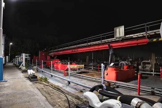
For an industrial buyer choosing among single-acting spring-return, double-acting double-rod, double-acting single-rod, rotary vane, and rotary rack-and-pinion actuators at a 200 bar working pressure, the practical cut lines are: single-acting for clamping and ejector work (lowest cost, no retract side); double-acting single-rod for press and lift where rod-side force is acceptable; double-acting double-rod where equal force both directions and zero net side-load matter; rotary vane for compact ≤270° swing with moderate torque; and rack-and-pinion for continuous-rotation indexing, large torque, and shock resistance. The hydraulic actuator form factor in the reference example [S3] is a single-acting rotating cylinder for a 120–275 rad/s duty on rotating shafts — exactly the niche where a vane or rack-pinion would not survive the centrifugal load.
A second cross-cut is duty environment. Mobile off-highway, factory floor, marine deck, and subsea each demand different rod coatings, seal compounds, and tie-rod vs welded body construction. Buyers who default to the cheapest NBR-sealed tie-rod cylinder for an outdoor mobile application end up replacing it inside 18 months; specifying HNBR seals, hard-chrome rod, and stainless fasteners on the same purchase order adds roughly 5–8% to unit cost and triples the service interval.
Step 6: Who Should NOT Pick the Cheapest On/Off Actuator
If the load changes mid-stroke, if the process needs repeatable position anywhere except end-of-stroke, or if the machine has a documented safety category above Category 1 (ISO 13849-1) on the actuator function, on/off control is the wrong tier — full stop. The same rule applies to any application with a documented cycle time under one second, a dynamic stiffness requirement, or a commanded motion profile that is not a simple trapezoid. In those cases, a proportional or servo hydraulic valve and matched actuator are the only defensible choice. [S1]
For buyers evaluating the broader motion-control stack, the working engineer's guide on electric actuator sizing is a useful counter-reference when the duty cycle is light, the cleanliness bar is high, or the install environment cannot tolerate a leak-prone hydraulic circuit. For context on the macro sourcing picture, the Hydraulic Cylinder Market 2026: $26B Outlook and Sourcing Map puts the 2026 industrial cylinder market at a $26B scale, while the Pneumatic Actuator Market 2026: Size, Spec Map, and Sourcing Signals is the right reference when the duty is light, the forces are below ~5 kN, and the buyer wants to drop the hydraulic power unit entirely. Hydraulic, electric, and pneumatic are complements, not substitutes — picking the wrong one wastes a capital line.
Step 7: Acceptance Test, Commissioning, and the Closing Sourcing Rule

Commission any proportional or servo hydraulic actuator against a written test plan that records step response, bandwidth, linearity, hysteresis, and internal leakage at three pressure points (typically 25%, 75%, and 100% of rated). A cylinder that holds 0.5 ml/min internal leakage at rated pressure is acceptable for general industrial duty; anything above 2 ml/min is not. For servo duty, also capture a frequency sweep at the operating pressure and a thermal soak at 100% duty for one hour — that is where most bench-acceptance failures surface, not in the first cold cycle. [S1]
Two trackable signals to watch: (1) whether the hydraulic power unit supplier offers a matched variable-speed pump package (VFD + internal gear or axial piston) — this is now mainstream for energy-sensitive industrial presses, and it materially changes the cooling and reservoir sizing the actuator spec must accept; (2) whether your hydraulic valve OEM publishes CAN J1939 or IO-Link command profiles in addition to 4–20 mA, because the migration off analog command is accelerating in mobile and machine-tool hydraulic circuits through 2026.