
A multifunction power meter is a single digital instrument that consolidates voltage, current, active/reactive/apparent power, power factor, frequency, energy, and often harmonics into one measurement point, replacing the stack of analog panel meters that used to crowd a switchboard [S1][S4].
The selection decision is driven by six concrete knobs: electrical topology (1-phase/3-phase 3-wire/3-phase 4-wire), current input method (direct connect vs CT/PT), accuracy class, demanded parameters, communication protocol, and physical mounting, all of which must be locked before any brand or model shortlist [S1][S2].
What a Multifunction Power Meter Actually Measures
Typical 3-phase multifunction meters sample per-phase voltage (L1-N, L2-N, L3-N) and line voltage (L1-L2, L2-L3, L3-L1), per-phase current (L1, L2, L3) plus the 3-phase average, and derive active power, reactive power, apparent power, power factor, frequency, and active/reactive energy from the sampled signals, with optional THD and individual harmonic orders on higher-tier units [S1][S4].
Current sensing is overwhelmingly done through external CTs on most low-voltage panels, because the meter's own inputs are typically 1A or 5A secondary (or 333 mV on Rogowski-friendly models), which keeps the metering circuit isolated from the busbar and avoids opening the power conductor to insert a shunt [S4]. Voltage is sampled at the meter terminals through potential transformers on MV systems, or directly on LV systems up to the meter's rated input, e.g. 480 V L-L or 690 V L-L on industrial DIN-rail units [S1].
The working chain is consistent across vendors: voltage and current transducers feed a metering IC, which integrates instantaneous power into energy and emits a pulse output proportional to kWh, while a separate MCU handles Modbus registers, alarms, and the local LCD [S4][S5].
Accuracy Classes and What the Numbers Mean on the Datasheet
Multifunction meters for revenue-grade or sub-billing work are commonly specified to IEC 62053-22 accuracy classes such as 0.2S, 0.5S, or 1.0 for active energy, where the "S" denotes extended dynamic range down to 0.05·In on CT-operated meters, while class 2 units are usually considered adequate for internal load monitoring only [S1].
Buyers should not confuse the energy accuracy class with the per-parameter accuracy of voltage, current, or power factor, which is often quoted separately as a percentage of reading plus a percentage of full scale (e.g. ±0.2% rdg ±0.05% FS) and is usually tighter than the energy class figure [S1]. For a feeder that may run from 10% to 120% of nominal, the class 0.5S and 0.2S "S" designations are the safer choice because the accuracy holds across that extended range, not just near full load [S1].
One common procurement trap: a meter advertised as "0.5 class" on the front page is sometimes specified as class 2 for energy and class 0.5 only for voltage and current, so the datasheet fine print must be read before comparing two units on price [S1].
Topology, Current Input, and Wiring Method
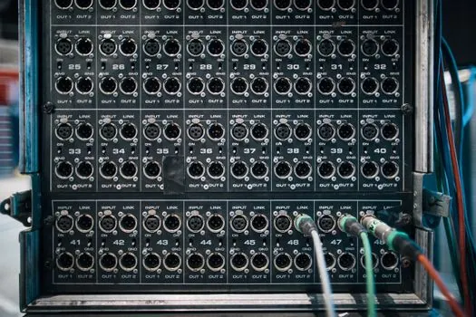
The first hard filter is the network topology. A single-phase 2-wire site needs a 1-phase meter; a 3-phase 3-wire (no neutral) motor feeder needs a 3P3W meter; almost every commercial and industrial building in practice runs 3-phase 4-wire, which mandates a 3P4W meter so that phase-to-neutral voltages and per-phase power factor are correctly computed [S1][S2].
The second filter is current input. Direct-connected meters are normally limited to 63 A, 100 A, or 200 A built-in, and are used for small commercial or branch-circuit monitoring where the conductor can be landed directly on the meter terminals [S1]. Above that, you must use CTs, and the meter's CT secondary (1A or 5A) plus the CT primary (e.g. 200/5, 400/5, 800/5, 1600/5) must be programmed into the meter so that its Modbus registers and display show engineering units, not raw CT secondary values [S1][S4].
For MV switchgear above 690 V, an additional PT (potential transformer) step is required on the voltage input to scale the meter to the actual primary voltage, and both the CT and PT ratios must be entered into the meter configuration [S5]. Misprogramming the CT ratio is the single most common field error and it scales every downstream number by the wrong factor, so the commissioning checklist should explicitly verify the ratio setting against the nameplate on every CT.
Selection Criteria: a 4-Option Comparison
For a typical 400 V L-L, 50 Hz industrial feeder, four realistic options line up as follows against the criteria that drive most purchase decisions [S1][S2][S6][S7]:
1. Basic panel meter (Class 1.0, V/I/PF/F only, no comms): low cost, suits local indication on a small MCC, but cannot feed an EMS or SCADA; usually falls short for any ISO 50001 energy review because the data is not exported.
2. DIN-rail multifunction meter with Modbus RTU (Class 0.5S or 1.0, full power/energy, RS485): the workhorse for plant-level energy monitoring; typically 96 mm x 96 mm or DIN-rail 4-module wide, supports CT primaries up to several thousand amps, and costs a small multiple of option 1.
3. Power analyzer class (Class 0.2S, harmonic analysis to the 31st or 63rd, waveform capture, Ethernet/Modbus TCP): required for PQ-sensitive sites (data centers, semiconductor fabs, hospitals), for IEEE 519-style harmonic surveys, and for proving power-quality compliance; roughly 3x to 6x the price of option 2.
4. DC multifunction meter (string monitoring for PV, DC bus monitoring for battery storage, or EV DC fast-charging): distinct category with Hall-effect or shunt DC inputs, typically 0.5% FS accuracy, and is not interchangeable with AC units because the metering IC, isolation, and CTs are AC-specific; for DC-side work, power meter selection must specify DC, not AC.
For most 400 V plant feeders, option 2 is the right answer; option 3 is reserved for PQ-mandated sites; options 1 and 4 cover narrow use cases (simple local indication or DC strings) where a full AC multifunction meter is overspec.
Communication, Integration, and EMS/SCADA Wiring
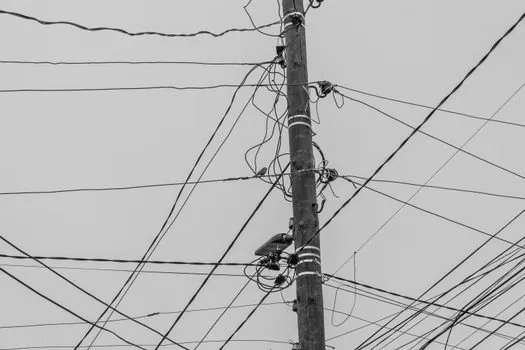
RS485 with Modbus RTU remains the default industrial fieldbus on 80% to 90% of installed multifunction meters, and the meter normally exposes 2-wire RS485 terminals with a switchable 120 ohm termination resistor and a node address settable from 1 to 247 [S1][S4]. For multi-drop buses, the maximum of 32 devices per segment is a real limit unless a repeater is inserted, and shielded twisted pair with a single ground point is the typical recommendation to keep surge and EMI out of the register data.
Ethernet variants (Modbus TCP, BACnet IP, IEC 61850 on grid-side meters, or PROFINET on automation lines) are common on higher-tier analyzers and on the meters specified for power distribution switchboards that already carry Ethernet to the SCADA cabinet. For solar PV plants, the same meter often also acts as a revenue-grade front end for the inverter data logger, in which case DNP3 or Sunspec compliance is sometimes required and should be specified up front [S1].
Pulse output (S0) and digital I/O are still useful as a hard-wired fallback to BMS or PLC counters when the bus fails, and as a calibration cross-check against a portable reference standard during commissioning [S4].
Who Should NOT Pick a Generic Multifunction Meter
Three buyer profiles are mismatched to a standard multifunction power meter and should look elsewhere. First, utility revenue billing at the Point of Common Coupling (PCC) usually requires a certified revenue meter with a metrology seal and a separate approval track; a multifunction meter is normally not accepted for billing, only for sub-metering behind the PCC [S1][S3]. Second, sites with a heavily distorted waveform (large VFDs, arc furnaces, large rectifiers) need a power-quality analyzer with flicker measurement and IEC 61000-4-30 measurement methodology rather than a basic THD-only meter [S1]. Third, DC strings on solar arrays, DC busbars on battery storage, and DC outputs of EV chargers require a DC-class meter; wiring a 333 mV AC Rogowski channel to a DC source gives zero reading and risks damage to the input [S3].
Buyers looking for a portable, clamp-on, single-instrument diagnostic tool for spot checks should also step away from the panel/DIN-rail multifunction category entirely and select a handheld power analyzer instead, since the panel-mount form factor is designed for permanent installation, not walk-around troubleshooting [S6].
Installation, Commissioning, and Field Pitfalls
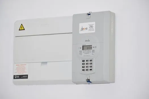
CT orientation and phase correspondence are the highest-risk items during commissioning. The CT arrow (or the marked primary side) must point toward the source, and the meter's I1 terminal must be wired to the same phase as the meter's V1 voltage input; cross-wiring V1 to phase A and I1 to phase B produces nonsensical power factor and active power readings even though all voltages and currents individually look correct [S1][S4].
CT polarity on 3-phase, 3-wire systems is especially unforgiving: even one reversed CT will not show up as a small error, it will show as negative power on that phase and a wildly wrong total, which is the most common reason a "broken" meter is returned to the factory when the meter itself is fine.
Other frequent field issues: the CT is sized so that normal load sits below 10% of CT primary (accuracy suffers, especially on non-"S" class meters), the CT burden is too high for the meter's input impedance and clips the waveform at harmonic-rich loads, and the neutral is not landed on a 3P4W meter so single-phase loads on L-N are computed with the wrong reference [S1][S2].
Shortlist Logic and Sourcing Signal
The shortlist can be reduced to a 3-line decision: confirm topology (1P/3P3W/3P4W) and CT secondary; lock the accuracy class (0.2S / 0.5S / 1.0) and the parameter list (do you need THD, individual harmonics, or just power/energy?); confirm the comms (Modbus RTU on RS485, Modbus TCP, BACnet, IEC 61850, or PROFINET) and the EMS/SCADA tag list that will consume the registers [S1][S2][S6].
Two trackable signals to watch in 2026 sourcing: the growing specification of Ethernet-APL and 5G-based wireless gateways on new-build chemical and data-center projects, and the wider adoption of class 0.2S meters driven by ISO 50001 energy reviews, both of which are pushing the spec floor up on tenders that previously accepted class 1.0. For cross-discipline buyers building a switchgear bill of materials, the related smart meter sourcing map and the counter equipment briefing sit alongside this selection logic. For a deeper dive into how multifunction meters compare with single-function energy meter and multifunction power meter variants on the same feeder, the spec-anchored entries on this site are the next node.