Sizing a steam trap is not a catalog pick, it is a five-variable calculation: steam pressure, backpressure, condensate load, startup multiplier, and trap type, then a chart lookup at the resulting differential pressure (DP) [S2][S3].
This article walks through the calculation order used on real plant work, the 2x and 3x startup factors, the 1% rule of thumb for steam main drips, and the trap-type comparison that drives the final selection on a steam trap [S3][S5].
Step 1: Define the condensate load in lb/hr at the steam pressure
The first number to lock in is condensate load in lb/hr at the operating steam pressure; for drip applications, the load is governed by steam pressure, ambient air temperature, insulation status, pipe diameter, and pipe schedule, and Watson McDaniel's sizing method makes these five inputs the basis of the calculated condensate load [S2].
For steam main drips specifically, the commonly cited rule of thumb is that each drain trap handles about 1% of the main's steam capacity when drip legs are spaced at roughly 50 m intervals and the line is well insulated, with recommended drip-trap spacing between 100 and 300 ft depending on layout [S2][S3].
Process equipment loads work differently: a batch reactor or heat exchanger at running conditions produces a steady condensate rate set by heat transfer demand, while the same unit at cold start can produce two to three times that running rate, and the trap must pass both, not just the steady-state number [S3][S5].
Step 2: Apply the startup safety factor (2x or 3x)
Once the running load is known, the next move is to multiply it by a startup factor that depends on how steam pressure is controlled: 2x the running load at working pressure (minus backpressure) for constant-pressure applications such as presses, ironers, unit heaters, radiant panels, and boiling pans, and 3x the running load at the running differential pressure for temperature-controlled applications where the full-load/minimum-load envelope is not well defined [S3].
Forbes Marshall's process work confirms the same envelope from the other direction: startup demand on batch operations is typically two to three times the running load, and single-orifice float traps cannot evacuate that slug, which is why two-orifice float designs exist specifically for the startup/running combined profile [S5].
The trap must also be sized for the air that has to be displaced from the equipment and adjacent piping when steam first enters a cold unit; this is why an air-venting function is typically required in the trap body for process heating service, not just for drip legs [S4].
Step 3: Correct capacity for the actual differential pressure
The manufacturer's capacity chart gives discharge rates in lb/hr at stated DP values, so the second calculation is the working DP across the trap itself: inlet steam pressure minus the effective backpressure on the outlet side, with the backpressure including both return-line pressure and any static head from vertical discharge (roughly 1 psi per 2.31 ft of vertical lift on the condensate) [S2][S3].
The Spirax Sarco worked example uses a 1.0 bar g steam inlet and a 0.5 bar g return to give a 0.5 bar DP across a ball-float trap at minimum load, illustrating that the same nominal trap selected at full DP is overrated at minimum load and underrated at startup, hence the factor from Step 2 [S7].
Capacity scales strongly with DP, so a 1.0 bar g trap derated to 0.5 bar g does not pass half the condensate, it passes a much smaller fraction because orifice capacity follows a square-root relationship; users should always read the corrected lb/hr from the chart at the actual DP, not at the inlet pressure [S2][S3].
Step 4: Match trap type to the application
Once the required lb/hr at the corrected DP is known, the choice of trap mechanism is driven by the application, not by capacity: float and thermostatic (FT) traps for process heating where continuous discharge and air venting are required, thermodynamic disc traps for steam mains and tracer lines where superheat tolerance and a small footprint matter, inverted-bucket traps for higher-pressure service with intermittent discharge, and bimetallic/balanced-pressure designs for subcooled discharge on tracer duty [S4].
Forbes Marshall's ISO 7841 / EN 27841 comparison numbers (1/2 in. traps at 5 barg) show that under no-load conditions the inverted-bucket trap loses significantly more steam than a float trap, and field results they report include a tyre press dropping from 17.91 kg/hr to 14.80 kg/hr per batch after a float retrofit, and a batch reactor reaching 60 C in 31 min versus 37 min while consuming 118.5 kg versus 161.5 kg of steam [S5].
For stall conditions, where a modulating control valve drops delivered steam pressure below backpressure and condensate flow stagnates, a pump-and-trap combination powered by a higher secondary pressure is the engineered fix, not a larger orifice [S4].
Step 5: Match the drain and discharge piping to the trap
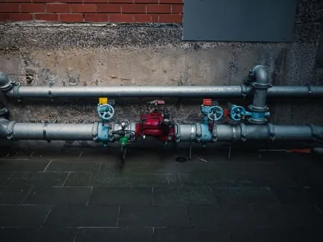
Trap size should closely match the size of the piping on the outlet side of the equipment that supplies condensate, not the equipment outlet itself, because the plant may operate at several pressures and flowrates, especially under temperature control, and the drain line is sized for condensate only with no flash steam in it [S3][S4].
Once the trap is selected, the drain line to the trap is normally the same size as the trap inlet connection, and the discharge line from the trap is sized to carry flash steam, not liquid; for drain lines under 10 m, the same pipe size as the trap is acceptable as a practical rule [S3].
For the discharge side, the Spirax Sarco sizing modules also cover common return lines (flash steam) and pumped return lines (condensate) as separate cases, and the sizing driver switches from DP to available NPSH on pumped returns, which is a different calculation path entirely [S3].
Criteria comparison: float, thermodynamic, and inverted-bucket on a process header
Stacking the three common industrial types against four decision criteria is the cleanest way to pick on a 5 barg process header: float/F&T traps win on continuous discharge and air handling, with energy loss per ISO 7841 typically 0.1-0.3 kg/hr at no load for a 1/2 in. unit; thermodynamic disc traps win on superheat tolerance and compact body, with typical 5 barg capacity around 600-900 lb/hr for a 1/2 in. unit but intermittent discharge that can log condensate on modulating service; inverted-bucket traps tolerate dirty steam and high backpressure but lose more steam at no load (often 1-3 kg/hr on a 1/2 in. unit at 5 barg per the same ISO test method) and discharge intermittently [S4][S5].
For drip-leg service on a steam main, the energy penalty of an inverted bucket at no load is small because drips run hot, and the dirt tolerance often matters more; for a temperature-controlled batch reactor, the float trap's continuous discharge is the correct match because condensate logging directly slows ramp-up, as the 31 min vs 37 min reactor case shows [S5].
Limitations, failure modes, and what to watch on a real audit
Common sizing errors include ignoring backpressure on the discharge side, which reduces the working differential pressure across the trap, using the nominal pipe size from the equipment outlet without checking the actual trap inlet, and omitting warm-up load considerations for startup conditions [S2][S3].
Stall, where the control valve chokes below backpressure, is a separate failure mode that no size increase fixes; the answer is a pump-trap with a higher secondary pressure, and confirming this requires reading the control-valve characteristic, not just the trap curve [S4].
Track these signals on the next trap survey: (1) actual inlet pressure vs nameplate at the trap, measured with a gauge at the inlet, not at the boiler; (2) return-line pressure at the trap discharge, especially on a shared return; (3) cold-start behaviour on the first 5 min of operation, where waterhammer or temperature lag indicates a startup-capacity miss; (4) trap body temperature vs downstream pipe temperature, where a cool trap on a hot line points to a plugged seat or wrong type [S4][S8].
For a deeper look at how fluid-handling hardware is specified alongside steam work, the spec reference on Industrial coating selection for corrosive plant equipment covers material-side decisions that often feed back into trap body material selection, and the ASTM D1002 lap shear test reference is useful when qualifying adhesive bonds on trap-station frames and insulation supports.
For component-level specifications, see steam separator, and electronic load.