A hydraulic accumulator is a nitrogen-precharged pressure vessel that stores energy by compressing inert gas against hydraulic oil, and the installation sequence (precharge, mounting orientation, safety-block plumbing, leak check) directly determines whether it survives its first 1,000 cycles or fails within weeks [S1][S3].
Three formats dominate industrial plants: bladder, piston, and diaphragm. Bladder units respond fastest and tolerate high cycle rates; piston units handle the highest pressures and hold gas longer; diaphragm units fit the smallest footprints [S4][S5]. Each requires slightly different precharge math, but the safety discipline is identical across all three.
Precharge Gas: Dry Nitrogen Only, Set Before Oil Entry
An accumulator precharged with oxygen, air, or any reactive gas can detonate when it contacts even trace hydrocarbon oil; nitrogen is mandatory because it composes roughly 78 percent of the atmosphere and is chemically inert against petroleum and synthetic hydraulic fluids [S3].
New units ship from the factory with zero precharge, so the installer must perform the first charge before the accumulator sees system oil. The accepted rule: precharge to roughly 0.9 x minimum working pressure for energy-storage duty, and 100 psi below minimum system pressure for piston units in shock-absorption service [S3][S5]. When OEM data is missing, charging to 50 percent of maximum system pressure is the documented fallback, not 80 percent, not 90 percent [S3]. For a wider primer on how an accumulator interfaces with a hydraulic actuator, the precharge pressure sets the gas spring constant that the actuator later works against.
Mounting Orientation, Bracket Position, and Vibration
Vertical mounting with a bracket located about two-thirds of the way up the shell is the standard recommendation across manufacturer and maintenance literature; this keeps the gas port up, the fluid port down, and prevents the bladder from sitting on the poppet under its own weight [S3].
Horizontal mounting is allowed for some piston-type accumulators but is explicitly discouraged for bladder designs because the bladder can crease against the shell wall. The bracket must clamp the cylindrical shell, never the end caps or the gas valve, and must allow thermal expansion of the steel shell across the working temperature range. For mobile equipment such as rough-terrain forklifts, the same bracket logic appears in the forklift installation guide: tracker, rough-terrain rigging, and electric commissioning, where accumulator clamps share the chassis with vibration-prone loads.
Plumbing, Safety Block, and Bleed-Down Path
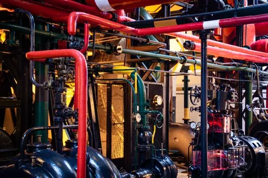
Every accumulator installation requires a manual shutoff, a safety relief valve, and a bleed-down valve between the accumulator and the rest of the circuit; without this trio the unit cannot be isolated, depressurized, or protected against overpressure events [S1][S2].
The relief valve set pressure must be at or below the accumulator's maximum allowable working pressure (MAWP) stamped on the nameplate, and the bleed-down must be piped back to tank, not to a dead-end header. Charging kits use a nitrogen bottle connected through a regulator, a charging hose, and a gas chuck that screws onto the Schrader valve; the gas chuck handle is turned clockwise to depress the pin and read the current precharge on the rig gauge [S3][S5]. If the measured value is too high, the rig's bleeder valve is cracked open to vent nitrogen to atmosphere until the target is reached; if too low, the nitrogen bottle valve is cracked open slowly to top up [S3]. The torque on the gas-valve protective cap is hand-snug only, no wrench, because over-torque damages the Schrader core.
Commissioning Sequence and Acceptance Criteria
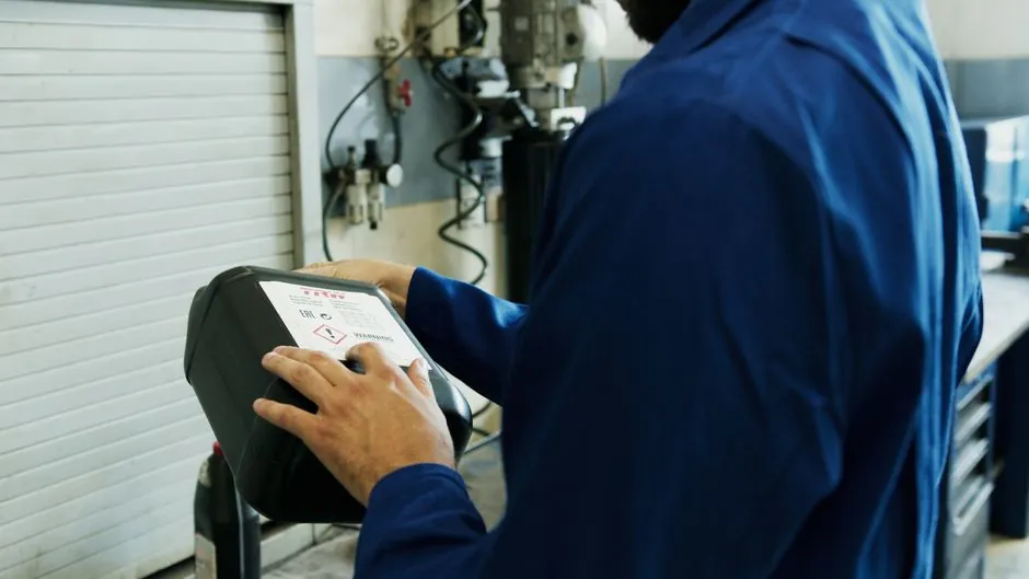
The documented commissioning sequence runs in this order: (1) inspect for shipping damage and verify part number, (2) read every label, sticker, and tag, (3) mount and plumb, (4) precharge with dry nitrogen, (5) leak-check the gas side with soapy water, (6) slowly fill the fluid side, (7) verify the safety block operates, and (8) cycle the system at reduced pressure before full duty [S1][S2].
Acceptance targets: gas-side leak rate of zero bubbles over 60 seconds at precharge pressure; fluid-side leak rate of zero visible drip over 5 minutes at operating pressure; precharge hold within ±5 percent of set value after a 24-hour rest. If the precharge drops more than 5 percent in 24 hours, suspect a Schrader core leak, a bladder perforation, or a piston seal bypass, and the unit must be removed from service before further cycling [S1][S3]. When the unit is part of a third-party OEM system, the OEM's commissioning instructions take precedence over the generic sequence [S2].
Type Comparison: Bladder vs Piston vs Diaphragm on Install Criteria
Across the three common designs, the install-time decision criteria differ sharply: bladder units offer the fastest dynamic response and tolerate flow surges up to their full rated flow, but require vertical mounting and periodic bladder replacement; piston units accept any orientation, hold precharge longer due to metal-to-metal sealing, but respond slower and cost more per unit volume; diaphragm units fit the smallest shells (typically under 1 litre), cost least, and are specified for low-cycle instrumentation and clamping circuits [S4][S5].
On precharge sensitivity, piston units tolerate the widest precharge deviation (±10 percent is common practice) because the piston has a defined end-stop; bladder units are more sensitive (closer to ±5 percent) because an over-precharged bladder can slam the poppet and cut itself; diaphragm units are the most sensitive and the least field-serviceable, so they are usually replaced rather than recharged [S3][S5]. On mounting, only piston designs are routinely installed horizontally; bladder and diaphragm designs default to vertical [S3]. On repair vs replace, piston seal kits and bladder cartridges are field-replaceable on most bladder and piston units, while diaphragm units are typically replaced as a complete assembly.
Failure Modes, Storage, and When NOT to Repair
The four recurring field failures are: (1) bladder cut from over-precharge or contaminated fluid, (2) gas-valve Schrader core leak, (3) poppet spring fatigue causing slow gas-side response, and (4) shell corrosion at the bracket clamp point from moisture trapped under the mount [S1][S3].
Repair-versus-replace thresholds from manufacturer guidance: replace the bladder if a pressure-hold test loses more than 10 percent precharge in 30 minutes; replace the poppet assembly if the gas-side response time increases by more than 50 percent versus nameplate; replace the entire accumulator if shell pitting exceeds 0.5 mm depth or if the nameplate MAWP stamp is illegible [S1]. For long-term storage (over 3 months), the unit must be partially precharged to roughly 30 percent of MAWP, capped, and stored in a dry, temperature-stable location; fully discharging a bladder unit for long-term storage can crease the bladder permanently and is a common cause of first-commissioning failures [S1]. Trackable signals for the next quarter: any new edition of the Parker HY10-2300 service manual, and any update to NFPA/T2 (Fluid Power Systems) section 6.7 on accumulator installation that revises the precharge tolerance band.
Spec-level background on the components involved: linear guide.