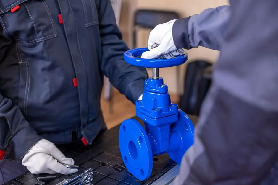
For HVAC overpressure protection, a spring-loaded pressure relief valve (PRV) with set pressure at or below the vessel maximum allowable working pressure (MAWP), sized per API Recommended Practice 520 and consistent with ASME Boiler and Pressure Vessel Code Section VIII Division 1, is the default specification across chilled-water, hot-water, and refrigerant service [S1][S3].
The valve must open at a predetermined set pressure, flow a rated capacity at a specified overpressure, and close when system pressure returns to a safe level, with the process fluid itself as the sole actuation source during power loss [S3]. Chilled-water expansion, boiler thermal expansion, and refrigerant high-side rupture are the three HVAC cases that most frequently drive a safety relief valve selection decision.
Set Pressure, MAWP, and ASME Section VIII Tolerance Bands
The pressure rating of the relief valve must be equal to or less than the MAWP of the vessel; most water heaters carry an MAWP of 150 psi, with some rated to 160 psi and plastic-piping storage tanks commonly rated 125 psi [S4].
For heating-hot-water service, model codes cap the T&P relief valve set pressure at 150 psi, which means a 160 psi MAWP vessel still needs a valve set at the code ceiling rather than at the nameplate pressure [S4]. Under ASME BPVC Section VIII Division 1, direct-acting spring-loaded PRVs must open at no more than 5% above the marked set pressure, and the set-pressure tolerance band is plus or minus 2 psi up to 70 psi and plus or minus 3% above 70 psi [S5]. These tolerance numbers are the same band that an HVAC plant owner will see in a valve calibration certificate, and they are the basis for any set-pressure audit on a fire safety walk-down.
Sizing Method: API RP 520 Capacity Correction for HVAC Fluids
Capacity correction factors in API RP 520 are empirically derived for the named fluid (air, water, steam) and require derating when the actual fluid is a glycol mixture, a brine, or a low-pressure refrigerant vapor that does not match the named-fluid data set [S3].
For a chilled-water PRV on a plate-and-frame heat exchanger, the required relief capacity is sized to the most onerous of: external fire case, blocked-in pump case with check-valve seat leakage, or thermal expansion of the full chilled-water inventory between the isolation valves [S6]. Sizing flows for hydronic service typically fall in the 50-500 gpm range for skid-mounted exchangers, with set pressures between 75 psi and 150 psi depending on the working pressure of the loop. The same valve is not interchangeable between a 100 psi glycol loop and a 150 psi hot-water loop without rechecking the capacity correction factor and the discharge reaction force at the new outlet size. Selection rules consistent with API RP 520 and ASME Section VIII Division 1 are reused across process, power, and HVAC service; the formulas are not HVAC-specific, only the load cases are [S1][S3].
Conventional vs Balanced Bellows: Back-Pressure Sensitivity in Plant Rooms

A conventional spring-housing PRV vents the spring housing to the discharge side of the valve, so its opening pressure, blowdown, and relieving capacity are directly affected by changes in discharge back pressure [S5].
A balanced-bellows PRV incorporates a means of minimizing the effect of back pressure on operational characteristics, which matters in HVAC plant rooms where multiple relief valves may discharge into a shared header that can see pressure swings during a simultaneous relief event [S5].
Decision rule: for a single-valve installation with a short, individually piped discharge to atmosphere, conventional PRVs are acceptable and cheaper; for shared headers, multi-valve manifolds, or any discharge run longer than roughly 3 m before the exit point, balanced-bellows is the default. Two practical HVAC cases: a rooftop boiler room discharging two T&P valves into a common vent through the roof needs balanced-bellows, while a single water-heater T&P at 150 psi / 210 F with a direct open drain does not. The T&P valve itself is a dual device that satisfies the code requirements of both a temperature relief valve and a pressure relief valve, with the temperature function controlled by an internal thermostatic element that drives the disc off the seat at 210 F [S4].
Capacity Criteria Comparison: Conventional vs Balanced-Bellows PRV
Both valve types open within the ASME 5% over-set band and both reseat on falling system pressure; the differences are concentrated in back-pressure tolerance, cost, and inspection access [S3][S5].
Conventional PRV: lower cost (typically 20-40% less than balanced-bellows in the same size and set-pressure class), sensitive to discharge back pressure, suitable for individual vent-to-atmosphere runs, and the spring-housing vent must be kept open and protected from weather and ice.
Selection criteria: if discharge back pressure is below 10% of set pressure and the fluid is clean water, steam, or air, conventional is fine. If discharge back pressure is above 10% of set pressure, or the fluid is a glycol/water mixture that can crystallize on the spring, balanced-bellows is mandatory. For ammonia refrigeration overpressure protection, the same comparison applies, and the cited ASHRAE 15 / IIAR 2 framework treats back-pressure tolerance as a primary selection input [S5].
Discharge Piping, Sizing Limits, and Chilled-Water Application
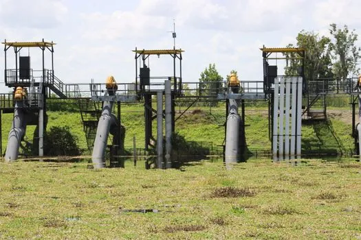
Discharge piping from the relief valve must be sized so that built-up back pressure does not choke the rated capacity, and the discharge must terminate in a location that does not endanger personnel or equipment [S5].
For closed chilled-water systems, a frequent under-sizing error is fitting the PRV to the heat-exchanger nozzle size rather than to the calculated required capacity, which on a plate-and-frame unit with a small nozzle produces a valve that is too small to pass the blocked-in-pump case flow [S6]. A separate failure mode is the chiller-tube rupture: a fully flooded chiller barrel exposed to suction-side pressure can produce a relief load equal to the full chiller inventory crossing the relief valve, and the PRV set pressure plus the discharge-line pressure drop must stay below the refrigerant-side design pressure of the chiller throughout the event [S6]. For refrigerant service specifically, ASHRAE Standard 15 and IIAR 2 are the governing frameworks, with rupture discs permitted as an alternative or in combination with a PRV where the fluid loss on a single relief event must be minimized [S5].
Installation, Testing, and Field Failures
A pressure relief valve is not a control or regulating device and should not be used to manage continuous thermal expansion in a closed system; thermal expansion must be handled by an approved expansion tank or by other code-permitted means, and a T&P valve that weeps continuously is a symptom of upstream sizing failure or debris fouling, not a normal operating state [S3][S4].
Set-pressure drift, seat leakage, and chatter on opening are the three most common field failures in HVAC service, and all three are typically detected during the ASME-required periodic bench test rather than in service [S1]. Mineral deposits, particularly calcium buildup on seats in hard-water heating loops, can render a T&P valve ineffective over time, and replacement intervals of 3-5 years are typical for water-heater T&P valves in high-hardness service [S4]. For PRVs on boiler and pressure-vessel service, field testing follows the lift-test protocol of API 576, with set-pressure verification, blowdown check, and visual seat inspection at each service interval. Process and HVAC plants share the same PRV technology stack and largely the same safety certification expectations; the practical differences are in the load-case list and the discharge-piping geometry, not in the valve itself [S1][S3].
Track the 2026 revision cycle of ASHRAE Standard 15 for any change to the ammonia and high-pressure refrigerant relief-vent sizing tables, and watch for any update to API RP 520 Part 2 on capacity correction for subsonic discharge piping, which directly affects how HVAC plant-room discharge headers are engineered.
See also our earlier report, Rough terrain forklift selection for mining: capacity, drivetrain, and ground-clearance.