Gas-charged accumulators are ubiquitous on modern hydraulic systems, performing energy storage, leakage and thermal compensation, shock absorption, and energy recovery [S1]. An accumulator lets a hydraulic circuit cope with peak demand using a less powerful pump, respond faster to short transients, and smooth pump pulsations, and it does this by holding hydraulic fluid under pressure applied by an external prime mover, spring, raised weight, or compressed gas [S4].
Because accumulators are pressure vessels with elastomeric or moving seals, they are maintenance items: pre-charge pressure, fluid cleanliness, and periodic inspection all determine service life [S1]. Selecting the right type means weighing compression ratio, response time, flow rating, mounting orientation, and contamination tolerance against the duty cycle.
Bladder Accumulators: Fast Response, Vertical Mounting
Bladder accumulators use a rubber bladder to separate the hydraulic fluid from the compressed gas pre-charge and are the most widely installed gas-charged design [S1]. They offer response under 25 milliseconds, a maximum gas compression ratio of roughly 4:1, and standard flow ratings up to 15 L/s (4 gal/s), with "high-flow" variants reaching 38 L/s (10 gal/s) [S1]. Their dirt tolerance is good, since particle contamination in the fluid has limited effect on the elastomeric element [S1].
The trade-off is mounting constraint: the preferred orientation is vertical, otherwise fluid can become trapped between the bladder and the shell and impair cycling [S1]. Bladders are also sensitive to pre-charge errors, a high or suddenly admitted nitrogen charge can chill the polymer to brittle failure or drive the bladder into the poppet on discharge, both common failure modes [S1].
Piston Accumulators: High Ratio, Any Orientation, Slower Response
Piston accumulators separate gas and fluid with a sliding piston and seal, and they tolerate the most aggressive duty envelopes. Maximum gas compression ratios reach 10:1 and flow ratings extend to 215 L/s (57 gal/s), far beyond bladder or diaphragm units [S1]. Because the piston is not gravity-dependent, the assembly mounts in any position, which simplifies skid and machine packaging [S1].
That capability has a cost. Response time exceeds 25 milliseconds, particularly at lower pressures, and the design exhibits hysteresis from piston-seal static friction and the inertia of the moving mass [S1]. The fluid must also be cleaner than what a bladder will tolerate, and improper pre-charge drives the piston to its end-of-stroke stop, with an audible warning that signals imminent seal damage [S1].
Diaphragm Accumulators: Compact, Limited Volume
Diaphragm accumulators share most of the bladder's fast-response character but improve on the compression ratio, reaching up to 8:1 versus the bladder's 4:1 ceiling [S1]. Their compact, lightweight form factor suits mobile and high-cycle applications where envelope size dominates the spec [S2].
The constraint is volume. Diaphragm units are generally limited to smaller displacements, and performance can drift over time as gas permeates across the diaphragm element [S1]. The same pre-charge discipline applied to bladders applies here, with slow nitrogen admission mandatory to avoid chilling the elastomer and to prevent extrusion into the gas valve on discharge [S1].
Comparison: Three Designs Against Four Decision Criteria
The three gas-charged types line up clearly when measured against the criteria that drive selection: maximum compression ratio, response time, peak flow, and mounting orientation. [S1]
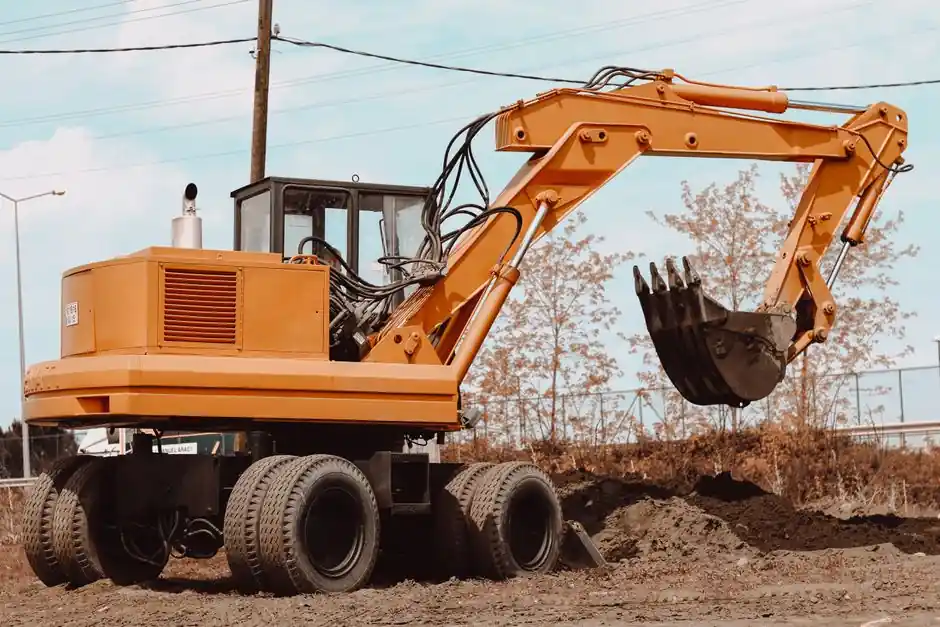
Bladder: 4:1 ratio, sub-25 ms response, 15 L/s standard / 38 L/s high-flow, vertical mount preferred [S1]. Piston: 10:1 ratio, over 25 ms response, up to 215 L/s, any orientation [S1]. Diaphragm: 8:1 ratio, sub-25 ms response class, lower flow / smaller volume, compact envelope [S1][S2]. For systems dominated by a brief high-flow pulse on a small reservoir, bladder or diaphragm wins; for long-duration high-ratio discharge on a heavy machine, piston is the right call, which is why piston and bladder units both appear in construction machinery and equipment such as excavators, cranes, and large mobile platforms [S2].
System-Level Benefits and Where They Pay Off
Storing energy in a gas-charged reservoir lets the pump run at a lower continuous flow, reducing energy consumption and giving the circuit a burst of power on demand [S2]. The same reservoir absorbs pressure surges and hydraulic shock, which protects pumps, valves, and downstream components from fatigue failure [S2]. This combination of pump-downsizing and shock suppression is the primary economic argument for fitting an accumulator in a new circuit.
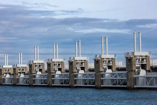
Typical duties include emergency power supply, pressure stabilization, pulsation damping on pump and valve outlets, and fast actuation of heavy loads [S2]. The same principle scales up to the largest hydraulic networks historically: nineteenth-century dock systems used raised water towers and weighted accumulators, with working pressures around 750 psi (5.2 MPa, 52 bar) powering cranes, bridges, and lock gates, a reminder that the hydraulic storage function is far older than the modern nitrogen-charged vessel [S4].
Limitations, Failure Modes, and Maintenance Discipline
Accumulators are pressure vessels, so in many jurisdictions periodic inspection, testing, and certification are not optional [S1]. Gas pre-charge pressure is the single most consequential maintenance variable: an excessive charge drives a bladder into the poppet assembly during discharge and is a common cause of bladder failure, while a low or zero charge lets system pressure crush the bladder into the shell, where it can extrude into or be punctured by the gas valve, a failure that takes a single cycle [S1]. Piston units are more tolerant of pre-charge error, but bottom-out impact still damages the piston and seal, with an audible knock as the warning sign [S1].
Charging procedure matters as much as the setpoint. Nitrogen must be admitted slowly; rapid expansion chills the polymeric bladder or diaphragm to a brittle state, and the high-velocity gas jet can also force the bladder beneath the oil-end poppet and cut it [S1]. Fluid cleanliness and pre-charge pressure together govern service life, which is why an accumulator in a well-maintained system can run for many years but becomes a recurring cost when either variable drifts.
Who Should Specify What
Bladder or diaphragm accumulators are the right answer for fast pulse-damping, mobile equipment, and any circuit where sub-25 ms response matters more than deep discharge: typical fits include clamping circuits, braking reservoirs, and the pulsation side of piston pumps [S1][S2]. Piston accumulators are the right answer where the cycle demands a high compression ratio, high sustained flow, or non-vertical mounting, including large machine-tool hydraulic actuators, offshore blow-out preventers, and the energy-recovery side of injection-molding presses [S1][S2].
Engineers designing safety-relevant circuits should expect regulatory oversight, since the unit is a pressure vessel regardless of type, and should plan a pre-charge check interval and a written charging procedure into the maintenance manual from day one [S1]. For larger site planning that pairs accumulators with rough-terrain lifts and other heavy iron, a rough terrain crane vs truck crane spec and site fit comparison is a useful adjacent reference.
Trackable signals to watch: pre-charge verification frequency on bladder-equipped fleets (a leading indicator of bladder life), and the share of new mobile hydraulic platforms quoting piston units over bladder units, which would indicate the industry accepting the cleanliness and hysteresis cost in exchange for higher compression ratio and orientation flexibility [S1].