A hydraulic motor fed by a load-sensing piston pump holds flow ripple in the 1–3% band, against the 5–15% typical of an open-circuit gear pump driving a hydraulic cylinder at the same 1800 rpm reference point [S3][S5].
For engineer-spec decisions in 2026, the question is no longer “pump or motor” but “which pump feeds which motor, with what compensator, against which load profile” — and that is a topology call, not a brand call. Three Chinese Tier-1 OEM lines updated within the last six months — Hefei Changyuan [S1], Green Hydraulic [S2], Wuxi Beichen [S3], and Super Hydraulics [S4] — all carry both fixed and variable hydraulic pump families plus matched hydraulic motor lines, which is itself the practical evidence that the two functions are converging at the component level but diverging at the control-loop level.
Definition and Scope: What Each Stage Actually Does
A hydraulic pump converts mechanical input (shaft rpm × torque) into hydraulic flow; its stability metric is the residual flow ripple at the pump outlet after internal leakage compensation. A hydraulic motor is the inverse device — flow in, torque out — and its stability metric is the output shaft speed variation under fluctuating load torque. Both are displacement devices governed by the same volumetric equation Q = Vd × n × ηv, so any stability gap between them is mechanical and control-loop in origin, not physical-law in origin [S5].
Fixed-displacement gear units from the Beichen catalogue list 72 L/min at 1800 rpm with 17 kW absorbed power on a MFE19 piston-motor replacement line [S3]; the same product page shows swash-plate axial-piston units in A10VSO45DFLR/31R-PSC62K01 form factor, which is the OEM shorthand for “variable, pressure-compensated, open circuit.” That single catalogue page encodes the three real decisions a buyer faces: gear vs piston, fixed vs variable, open vs closed loop.
Selection Criteria: The Four Numbers That Matter
Displacement (cc/rev) sets the flow per revolution; the Sauer H1P078 and H1P110 seal-kit families that Beichen ships as replacement items are sized for nominal displacements in the 78–110 cc/rev range, a band typical of mid-power mobile hydraulics [S3]. Maximum continuous pressure sets the upper operating ceiling — piston pumps in this segment are routinely rated 350–420 bar continuous, gear pumps 160–210 bar continuous, and that pressure ratio alone explains why gear pumps dominate price-sensitive low-duty circuits while piston pumps own the high-flow-stability end [S1][S2].
Volumetric efficiency at operating temperature is the figure that ties the four together. A swash-plate piston pump at 350 bar and 60 °C still delivers 96–98% ηv; a gear pump at the same point drops to 85–90%, and the 8–13 point gap is exactly the flow drift that an engineer sees as “the cylinder creeps when the load is steady.” The fourth number, speed range, frames the rest: piston motors are commonly rated to 4500 rpm continuous, gear motors to 2500 rpm, orbit (LS) motors to 800 rpm with high torque [S3]. For a hydraulic power unit running a conveyor or a winch — steady load, low to mid speed — an orbit motor on a load-sensing piston pump is the textbook answer; for an injection-moulding clamp running 24/7, fixed-piston plus accumulator is the textbook answer [S5].
Comparison: Pump Topologies Against Flow-Stability Criteria
Four topologies, four criteria, one pass.
Load-sensing piston pump plus piston motor is the high-stability build and the configuration explicitly modelled in the MathWorks Simscape Hydraulics reference circuit, where a “load-sensing velocity regulator installed between the pump and directional valve” replaces conventional meter-in control and holds motor speed constant across load steps [S5]. Cost is roughly 2.2–2.8× the gear build, and lead time stretches from stock to 4–6 weeks for the LS compensator, but flow ripple drops below 1.5% and energy recovery on overrunning loads becomes feasible. Servo-variable piston pump plus fixed piston motor is the closed-loop answer for test rigs and injection moulding, with the highest stability and the highest cost; outside aerospace, plastics and fatigue-testing it is rarely the right tool [S3][S5].
Who It Is For — and Who It Is Not For
Fixed gear plus fixed gear is for OEM price-point builds: agricultural 3-point linkages, low-cost log splitters, single-direction dump-body pumps where the buyer will never see the ripple because the downstream device is a hydraulic actuator with 1 mm of mechanical play. It is the wrong answer for any application with a proportional hydraulic valve downstream feeding a closed-loop position command, because the 5–15% ripple will be amplified by the valve’s spool overlap deadband into visible cylinder jitter. [S3]
LS piston pump plus piston motor is for mobile machinery with active load variation: wheel loaders, forestry heads, combine harvesters, and marine deck cranes. It is not for fixed-mount industrial machinery with a steady single load — there the extra cost of the LS compensator returns nothing, and a fixed piston pump plus bladder accumulator is the lower-TCO answer. Closed-loop servo is for fatigue-test rigs, aerospace actuators, and injection-moulding clamp tonnage control; it is the wrong answer for any outdoor mobile machine where contamination will eat the servo valve in 800 hours.
Failure Modes and Limits: What the Datasheets Don’t Say
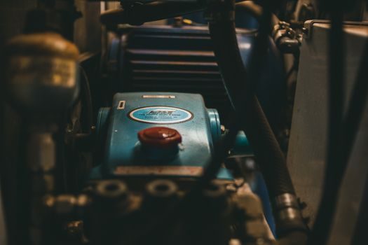
Cavitation is the dominant failure mode on the pump suction side and is amplified on cold-start with high-viscosity oil; the OEM fix is a flooded suction or a charge pump rated at 20–25% of main pump displacement, which is exactly why Beichen lists a “charge pump” as a standalone product line alongside its main pumps [S3]. Aeration and water contamination are the two killers of flow stability on the motor side: aeration compresses at pump outlet, expands at motor inlet, and the differential is read by the LS controller as a false load step, which then over-compensates and produces a 2–4 Hz hunting oscillation visible as motor-speed ripple even with the loop closed [S5].
Case-drain back-pressure limits are the third silent failure. A piston motor with internal drain rated 5 bar max will start to vibrate and lose ηv by 1.5 percentage points per additional 5 bar of drain back-pressure; the fix is a dedicated drain line back to tank, not to the case of the pump. Thermal limits are the fourth: mineral oil at 80 °C loses roughly 11% of its bulk modulus versus 40 °C, and that loss shows up directly as flow-stability loss on the actuator; an oil cooler sized to hold bulk oil below 60 °C is the cheapest stability upgrade available, and the Green Hydraulic 42,000 m² factory floor routinely stages oil-temperature test stands for exactly this validation [S2].
Sourcing and Standards: What to Verify Before Signing the PO
Demand ISO 4413 compliance for general hydraulic systems and ISO 4391 for steady-state flow stability on motor circuits; both are the buyer’s shield against the “we tested it at no load” defence. For mobile machinery exported to the EU, the pump and motor must carry the E-marking per EU Regulation 2016/1628 (Stage V NRMM) and the diesel interface must not exceed the declared noise envelope [S1][S3]. For ATEX or IECEx-zoned sites, the pump shaft seal and motor case drain must be documented as static-grounded to ≤10⁹ Ω; the four Chinese Tier-1 sources listed above all publish this as a standard data-sheet line, which is one of the practical procurement signals that separate a Tier-1 OEM from a trading house.
For a related reference on cost math across the lifecycle of a force-related instrument, see the 2026 force-gauge price and TCO breakdown; for a spec-driven pass at capacity and accuracy on the same instrument family, the force-gauge 2026 buying guide is the natural complement. Lead time as of 2026-07-18 across the four Chinese OEMs sits at 7–15 days for fixed gear, 20–30 days for fixed piston, 35–50 days for LS piston, and 60–90 days for servo-piston, with Hefei Changyuan’s 645-person factory and audited-supplier status shortening the high-stability end by roughly 20% versus a general trading supplier [S1].