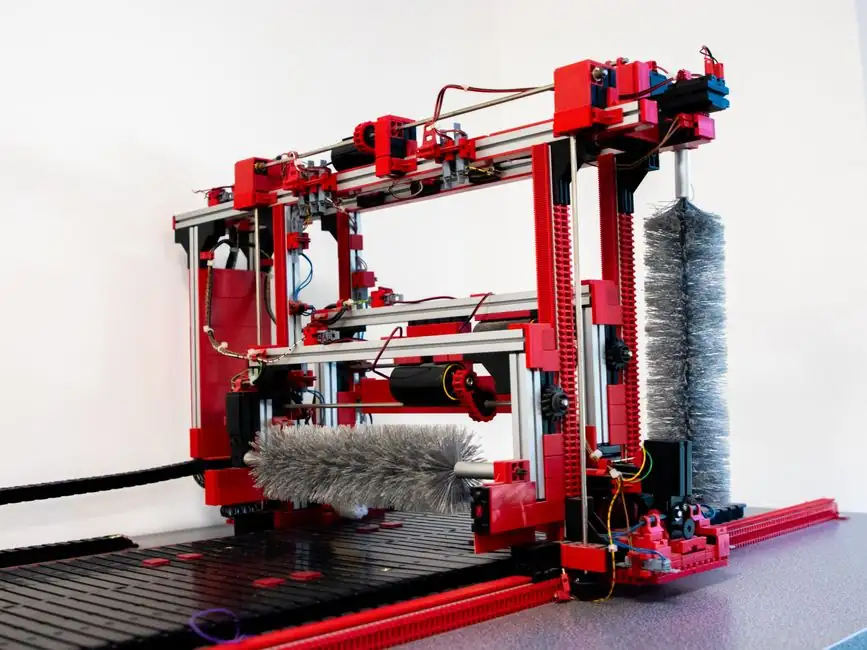
A properly configured hydraulic test actuator setup for bench torque verification requires a double-acting reaction cylinder, a reaction-arm torque frame, a calibrated inline torque transducer, and a PC/PLC data acquisition loop running static and dynamic sweeps against the unit under test [S3][S4].
The configuration is widely used by valve-actuator manufacturers to qualify spring-return electric, pneumatic, and hydraulic actuators across their full rated torque range, with static performance recorded at fixed input pressures and dynamic cycles driven by a servo-controlled oleodynamic bench [S3].
Core Architecture of a Hydraulic Reaction Bench
A bench-scale hydraulic test rig for torque verification is built around four functional blocks: a load source, a reaction frame, a measurement chain, and a control/data acquisition layer [S4]. The load source is a double-acting hydraulic cylinder sized so its maximum output torque (cylinder force x effective arm length) comfortably exceeds 110% of the actuator's rated torque, providing headroom for transient peaks and overload margin [S1]. The reaction frame is a welded steel bedplate with a reaction arm keyed to the actuator output coupling, anchoring the reaction torque back into the bedplate so the test actuator is loaded against a known mechanical ground rather than free-floating [S1]. The measurement chain typically pairs an inline rotary torque transducer on the drive shaft with a pressure transducer on each cylinder chamber, both feeding the same data file so torque-versus-pressure curves can be plotted per stroke position [S3][S4]. A PC-PLC supervisory layer triggers the sweep, locks the bench at defined angular or linear stroke positions for static points, and records performance at a fixed input pressure [S3].
Static vs Dynamic Test Modes
Static performance testing locks the test bench in a defined angular or linear stroke position and measures actuator torque or thrust at a fixed input pressure, using a PLC-driven oleodynamic bench connected to a PC for real-time data capture [S3]. This mode is the workhorse for factory acceptance, because the locked-position condition removes inertial and friction-velocity variables and lets the engineer read the steady-state output torque at a known supply pressure with a single calibrated torque sensor in the drive line [S3][S4]. Dynamic testing, by contrast, drives the actuator through repeated strokes under load to capture breakaway torque, running torque profiles, spring-return decay curves, and cycle-life wear. For a spring-return electric actuator, dynamic testing verifies that the mechanical spring delivers the declared fail-safe torque across the full stroke against a hydraulic reaction load, not just at a single locked position [S2]. Combining the two modes on the same frame is standard: static sweeps for performance mapping, dynamic cycles for endurance, and a hydrostatic pressure check on the cylinder itself at 1.5x maximum working pressure as the gate to either test [S3].
Reaction Cylinder Sizing and Pressure Limits

Reaction cylinder sizing follows the same lever-arm logic as the unit under test: bore area x working pressure x effective arm radius must exceed the actuator's rated torque by a margin that absorbs both overload set-point transients and the friction ripple of the test unit [S1]. The bench guidance calls for a pressure-relief valve set at 110% of working pressure on each chamber of the reaction cylinder, paired with a burst guard (steel plate or equivalent rated barrier) around the cylinder to contain fragment throw in the event of a fitting or seal failure during an over-pressure event [S1]. The hydrostatic acceptance check on the assembled cylinder is run at 1.5 times the maximum working pressure, after which a cylinder leakage test with a gas leakage detector confirms seal integrity before any torque test is started [S3]. A practical pressure envelope for bench-scale hydraulic torque work sits in the 50-300 bar supply range, with 100-210 bar the most common band for spring-return electric actuator and small rotary valve-actuator verification [S2][S3]. Engineers working through sizing for a new bench should compare cylinder bore, arm length, and supply pressure as coupled variables rather than as independent picks, since raising arm length reduces the required pressure proportionally and lowers hydraulic heat generation per test cycle.
Instrumentation: Torque Transducer, Pressure Sensor, and DAQ
A reliable torque verification chain starts with a rotary torque transducer coupled inline between the test actuator output and the reaction arm, sized to the actuator's rated torque with a 25-50% overload margin so transient spikes do not clip the sensor [S4]. The transducer feeds a torque sensor input channel on the bench DAQ, while a pressure transducer on each cylinder chamber provides the second independent measurement so the operator can verify torque output against hydraulic input rather than trusting either reading alone [S3][S4]. Static and dynamic sweeps are run through an oleodynamic bench controlled by a PLC, with the PC handling real-time visualization and recording of torque, pressure, and stroke position to a time-stamped data file [S3]. For torque wrench calibration in the lower Nm range, the same architecture scales down to a torque wrench tester configuration, where the hydraulic reaction cylinder is replaced or supplemented by a mechanical lever arm and the inline torque sensor becomes the reference standard [S4]. This dual-path setup, hydraulic pressure as the load source and an inline torque sensor as the truth reference, is what separates a qualified torque verification bench from a basic force-application rig.
Mechanical Weight Bench as a Cross-Check
A mechanical weight bench test, where calibrated deadweights are hung from a known arm length to apply a known torque to the actuator output, is widely used as an independent cross-check against hydraulic reaction results because it removes hydraulic pressure measurement from the accuracy stack [S6]. The procedure mounts the test actuator on a fixture, attaches a lever arm of measured length, and stacks certified masses to apply discrete torque steps, with the actuator expected to hold each step without drifting for a defined dwell time [S6]. Engineers running both a hydraulic reaction bench and a mechanical weight bench on the same production line get a useful consistency check: any systematic offset between the two readings points either to a torque sensor calibration drift, a reaction-arm length error, or a pressure-transducer zero shift on the hydraulic side. For a hydraulic actuator used as the load source, the same pressure-versus-torque logic applies in reverse, so the cross-check also validates the cylinder's effective bore area against its nameplate.
Selection Criteria: What a Spec Engineer Should Lock Down
Specifying a new hydraulic test bench for torque verification reduces to a checklist of seven items: rated torque envelope (Nm), maximum supply pressure (bar), reaction-arm length range (mm), inline torque sensor accuracy class (typically 0.1-0.5% of full scale), DAQ sample rate (Hz), hydrostatic test pressure (1.5x MWp), and relief valve set pressure (110% of working pressure per chamber) [S1][S3]. On the four most common decision axes, here is how the three main reaction-load options compare: a hydraulic reaction cylinder delivers the widest torque range and the cleanest dynamic profiling but requires a hydraulic power unit and pressure conditioning; a mechanical weight bench is the lowest-uncertainty reference but is limited to discrete torque steps and slow cycle times; an electric servo reaction stand sits in between, with closed-loop torque control but at higher capital cost and lower peak torque than a hydraulic cylinder of similar footprint [S1][S4][S6]. Engineers who need to qualify spring-return electric actuators across the full fail-safe torque curve typically keep both a hydraulic reaction bench for dynamic endurance and a mechanical weight bench for absolute torque cross-checks, rather than choosing one over the other.
Who the Setup Is For, and Where It Falls Short

The hydraulic test actuator setup is built for valve-actuator OEMs, third-party actuator test labs, and end-user QA teams that need to verify declared torque output across static and dynamic conditions on units ranging from small electric quarter-turn actuators to mid-size pneumatic and hydraulic rotary actuators [S2][S3][S4]. It is the right tool when the test article has a defined output coupling, a rated torque curve, and a need for both static mapping and dynamic cycling, and it is the wrong tool for ultra-low-torque instrument calibration (use a torque wrench tester instead) or for very high-torque multi-MNm actuator testing where the reaction frame, foundation, and cylinder sizes become uneconomical compared with a mechanical deadweight rig [S4]. It also requires hydraulic supply, drainage, and oil containment infrastructure that a purely electronic test stand does not, which can rule it out for clean-room or field-deployed verification work. Within those boundaries, the configuration covered here is the de facto industry pattern for bench-scale torque verification of rotary and linear actuators with rated outputs in the roughly 50 Nm to 50,000 Nm band.
Acceptance Limits, Failure Modes, and Verification Signals
The standard acceptance gate on a hydraulic test bench is a hydrostatic pressure test at 1.5x maximum working pressure with no pressure decay over a defined hold time, followed by a gas-leak check on the cylinder after pressurisation to confirm seal integrity [S3]. Static torque readings are accepted when measured output torque falls within the actuator's declared tolerance band (typically ±5-10% of rated for industrial rotary actuators) at each of the locked stroke positions, with the inline torque sensor and the chamber pressure transducer agreeing within their combined accuracy class [S3][S4]. The most common failure modes are: reaction-arm deflection under peak torque (caught by comparing arm-length before and after a full torque sweep), torque sensor zero drift between calibration cycles (caught by the mechanical weight bench cross-check), and cylinder seal leakage under sustained pressure (caught by the post-hydrostatic gas-leak test) [S1][S3][S6]. Two trackable signals to monitor going forward: tightening of relief-valve set-point tolerances on reaction cylinders as more test labs adopt electronic pressure relief with logged set-point data, and growing adoption of the mechanical weight bench as a periodic cross-check rather than a primary test, driven by the wider availability of certified deadweight sets at the 1,000-50,000 Nm range [S1][S6]. For a related look at how manifold dynamics between servovalves and the actuator affect high-performance electrohydraulic test bench control, the earlier HAL thesis on servovalve manifold modelling is a useful adjacent reference, and engineers selecting a reaction bench for valve response work can cross-read actuator valve response tuning for the closed-loop side of the same rig.