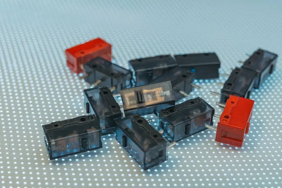
Inductive proximity sensors routinely deliver 100 Hz to 5 kHz switching frequency, while capacitive sensors in the same M12 to M30 barrel size typically reach only 10-100 Hz, a 10x to 50x gap that dictates high-speed line design [S4][S5].
The reason is physics, not marketing: the inductive LC oscillator damps and recovers in microseconds, whereas the capacitive front-end needs to track slower dielectric relaxation through its electrode field, which limits its on/off cycle rate [S3][S6]. For a process engineer sizing a parts counter, that means inductive is the default for metal-on-conveyor work above 50 targets per second, and capacitive is reserved for liquid level, granulate, or non-metal targets where speed is not the constraint [S1][S3][S7].
Switching Frequency: Definition and the Rated vs Usable Gap
Switching frequency, expressed in Hz, is the maximum number of complete on/off cycles a proximity sensor can perform per second, and it is the inverse of the sensor's response time, which is specified in milliseconds or microseconds [S4]. A sensor rated at 1 kHz can complete 1,000 detection cycles every second; a 5 kHz inductive unit can complete 5,000, which is the range that most M12 inductive proximity switches from mainstream European catalogues occupy [S4].
The datasheet number, however, is measured under laboratory conditions: stable temperature, no EMI, a standardized target, and optimal mounting distance, so the real-world usable frequency in most plants falls to 30% to 60% of the rated value [S5]. Dust, oil mist, humidity, temperature drift, electrical noise, vibration, and small or irregular targets each chip away at that headline figure, and a sensor running at the edge of its rated frequency will start to miss detections, double-trigger, or jitter the PLC input [S5]. A practical rule: if the interval between two targets approaches the sensor's response time, missed counts are likely, no matter what the datasheet claims [S5].
Why Inductive Switches Faster: LC Oscillator Physics
An inductive proximity sensor's active face is a coil that forms part of an LC oscillator; when a metal target enters the field, eddy currents drain energy from the tank circuit and the oscillator amplitude collapses, which the trigger stage converts to a switching output [S3]. The collapse and recovery are dominated by the L and C values, both of which are small and tightly coupled, so the cycle settles in tens to hundreds of microseconds, which is what allows 1 kHz to 5 kHz part numbers to exist in standard M12 and M18 housings [S3][S4].
IO-Link inductive sensors expose additional diagnostic data, including internal temperature and a cumulative switching-cycle count, which lets maintenance staff trend real cycle rates against the rated figure instead of trusting the label on the box [S3]. This is also where the inductive sensor family differentiates itself from the capacitive sensor family, since the latter cannot match the inductive cycle rate because its sensing element is a capacitor plate, not a coil, and its target is the dielectric, not eddy-current loss [S1][S3][S6].
Why Capacitive Trades Speed for Material Flexibility
A capacitive proximity sensor measures the change in capacitance between an active electrode and a reference electrode; any material with a dielectric constant different from air (water at ~80, paper at ~2, plastic granules at ~1.5-4) shifts the oscillator and triggers the output [S6][S7]. Because the capacitive front-end must charge and discharge a relatively large electrode area through whatever medium sits in front of it, the recovery time is longer, and switching frequencies cluster in the 10-100 Hz band for M18 and M30 barrels, with some specialised liquid-level versions going even lower to reject splashing and foam [S1][S4][S6].
The payoff is material reach: a capacitive sensor will see wood, cardboard, glass, plastic, oil, and water through a non-metallic housing wall, which an inductive sensor cannot do at all, since inductive fields only couple to conductive (eddy-current) targets [S1][S3][S6]. The capacitive sensor datasheet will quote a sensing distance based on a grounded metal target, and the same part number will reach roughly half that distance against water and a fraction of that against dry paper, which is why tank-level, hopper-level, and label-on-bottle applications default to capacitive even with the speed penalty [S1][S7][S8].
Decision Matrix: Inductive vs Capacitive on Speed, Range, and Target
On switching frequency, inductive scores 100 Hz to 5 kHz typical and capacitive scores 10-100 Hz typical, a 10x to 50x advantage for inductive that holds across M8, M12, M18, and M30 barrel sizes [S4][S5][S7]. On sensing distance for a given barrel, inductive reaches further on its native target (steel) because the coil field is well-matched to eddy-current damping, while capacitive reaches further on non-metals because it actually responds to them at all [S7][S8].
On target material, inductive is restricted to ferrous and non-ferrous metals with a derating factor (often 0.3-0.8 of the rated Sn) for stainless steel, aluminium, and copper, while capacitive covers metals plus plastics, liquids, wood, paper, and glass, including through thin non-metallic walls [S1][S3][S6][S7]. On environment, inductive tolerates much more oil, coolant, and weld-splash contamination because the electromagnetic field is contained inside a sealed face, while capacitive can be fooled by humidity, condensation, and material build-up on the electrode, since those change the baseline dielectric [S1][S3][S7]. For high-speed metal counting on a conveyor, specify inductive at 1 kHz minimum, derated to 500 Hz usable; for non-metal level detection through a tank wall, specify capacitive at 25-50 Hz and accept the speed limit [S4][S5][S7].
Use Cases Mapped to Switching Frequency
High-speed metal parts counting on a bottling or assembly line typically runs at 200-2,000 targets per second, which is squarely in the inductive 1 kHz to 5 kHz band, and the same logic applies to gear-tooth sensing on rotating shafts, where a displacement sensor or inductive proximity switch tracks each tooth edge [S2][S4][S5]. At 8 m/s line speed, a 25 microsecond response time (40 kHz-rated contrast sensor, used here only as a math anchor) corresponds to a 0.2 mm spatial resolution, which is why pharmaceutical label verification uses kHz-class photoelectric rather than slower proximity technology [S2].
Typical cycle rates in those applications sit below 10 Hz, so the capacitive 10-100 Hz ceiling is comfortable, and the engineer gains material flexibility, not speed [S4][S7]. For a deeper look at how target metal composition shifts the usable range on the inductive side, see this reference on inductive sensor sensing distance behaviour with different target metals.
Failure Modes and Selection Traps
Missed detection at high line speed is almost always a switching-frequency mismatch, not a sensor defect, and the fix is either slowing the line, choosing a higher-frequency part, or moving the sensor closer to the target to widen the dwell time [S2][S5]. Double counting and signal jitter trace to the same root cause: the sensor is being asked to cycle faster than its usable frequency in the installed environment, and the output stage toggles multiple times per target pass [S5].
Capacitive-specific traps include false triggers from condensation, foam, and material build-up on the electrode, and a sensing distance that collapses when the target dielectric constant approaches that of the surrounding air; inductive-specific traps include the 0.3-0.8 Sn derating for non-ferrous targets and complete blindness to any non-conductive material [S1][S3][S7]. EN 60947-5-2 defines the inductive switching distance against a standardized 1 mm-thick mild-steel calibrating plate, so any factory-acceptance test should reproduce that plate and that approach speed, otherwise the published Sn number is not what is being measured [S3].
Sourcing, Standards, and Trackable Signals
Inductive sensor switching frequency is specified per EN 60947-5-2, which also fixes the test target geometry, approach speed, and ambient conditions, and that standard is the right cross-reference for any procurement spec on a European line [S3]. Capacitive sensors fall under the same low-voltage switchgear standard family for electrical ratings, but their sensing-distance convention is manufacturer-specific, so the datasheet's quoted Sn for a given target material (steel, water, plastic) must be carried into the purchase order verbatim [S3][S7].
Watch for the IO-Link revision on inductive data sheets (currently COM3 / 230.4 kbit/s on most 2026 releases) since the diagnostic switching-cycle counter and internal temperature readout only come through the digital channel, and a 4-wire analogue inductive will not expose them [S3]. For applications sitting at the 30%-60% usable-frequency boundary, log the actual cycle count over a one-week trial before signing the PO, and derate the rated figure by at least 50% for any environment with oil mist, EMI, or temperature swing above +/-10 K [S5].