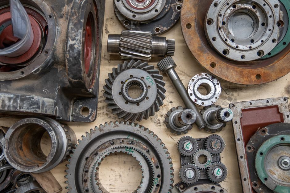
Gears are mechanical power-transmission elements classified chiefly by the relative position of their axes, and a working spec engineer needs that taxonomy before any material, hardness, or AGMA/ISO rating is written on a drawing [S3].
Within parallel-axis gearing — spur, helical, internal, and rack forms — the same basic involute tooth geometry is shared, while intersecting-axis bevels and skew-axis worm pairs introduce fundamentally different tooth-action kinematics that change lubricant, bearing, and housing requirements [S3].
Parallel-Axis Gears: Spur, Helical, Internal, Rack, Double Helical
Spur gears carry teeth parallel to the axis and remain the most common, easiest-to-manufacture cylindrical gear, with tooth traces that are straight lines parallel to the shaft axis [S3]. Helical gears replace that straight trace with a helix curve, giving higher tooth strength, lower oscillation, and reduced noise, but at the cost of an axial thrust load that reverses with rotation direction [S3]. Double helical gears are effectively two helical gears joined together and cancel the net axial thrust, which is why they appear in heavy-duty parallel-shaft drives [S3].
Internal gears are cylindrical rings with teeth cut on the inside diameter and are most often seen as the ring (annulus) member of a planetary gear train; both parallel and helix-trace versions exist, with the parallel-tooth version carrying the higher market demand [S3]. A straight rack is what a spur gear becomes when its pitch radius grows to infinity — a flat bar of involute teeth that mates with a spur pinion to convert rotary motion into linear travel, with a helical rack being the matching infinite-radius helical counterpart [S3].
Intersecting-Axis Gears: Straight Bevel, Spiral Bevel, Zerol, Face
Intersecting-axis gears transmit power between shafts whose axes cross (typically at 90°), and the straight bevel — also called a miter gear when the ratio is 1:1 — is the baseline form, with its tooth trace running as a straight line along the pitch-cone surface element [S3]. When the shaft angle is not 90°, the same straight-tooth geometry becomes an angular straight bevel gear, retaining the simple cutting process at the cost of asymmetric loading [S3].
Spiral bevel gears curve that tooth trace into a spiral, lifting tooth strength, oscillation, and noise behaviour above the straight bevel; the trade is an axial thrust load that demands proper bearing location and a rigid housing [S3]. Zerol® bevel gears are a Gleason trademarked subset with zero spiral angle (sometimes extended to ~10°) that keeps the same tooth-action force pattern as a straight bevel while remaining machinable on spiral-beel equipment [S3]. Face gears are toothed disks that mesh with a spur or helical pinion, available in both 90°-intersecting and non-intersecting shaft arrangements, and are common where a large offset between input and output shafts is required [S3].
Skew-Axis (Non-Intersecting) Gears: Cylindrical Worm, and Beyond
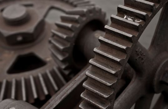
Skew-axis gears transmit power between non-intersecting, non-parallel shafts, and the cylindrical worm gear pair — a cylindrical worm meshing with a worm wheel — is the canonical industrial form, where the worm thread can have one or more starts that set the speed ratio [S3]. Worm pairs provide high reduction ratios in a single stage and a self-locking tendency depending on lead angle, but at the cost of sliding contact, which drives the choice of bronze worm wheels, hardened-steel worms, and EP (extreme-pressure) gear oils rather than the splash lubricants common in enclosed spur/helical units [S3].
Beyond the cylindrical worm, hypoid and crossed-helical (skew) gears extend the skew-axis class, but the source material restricts the explicit taxonomy to cylindrical worm pairs, treating the rest as derivative geometries [S3]. For a working spec engineer, the practical rule is that any skew-axis drive with significant sliding contact must be evaluated for thermal capacity, worm-wheel material (often a centrifugal-cast tin or aluminum bronze), and worm hardness (typically case-hardened or through-hardened alloy steel) before duty cycle is locked in. Related coverage of worm-gear reducer materials and spec boundaries walks through how those worm-pair constraints cascade into gearbox selection.
Manufacturing-Method Classification: Machined, Formed, and Beyond
A second axis of classification — and the one that drives lead-time and cost — is the manufacturing method: machined gears use hobbing, gear shaping, gear planing, or broaching (broaching for mass production of spur and helical teeth), while bevel gears require dedicated cutting machines because their tooth geometry cannot be produced on a standard hob [S3]. For parallel-axis spur and helical gears, hobbing is the high-volume default and is the reason a stock 1.0-module spur pinion ships in days rather than months. Machined gears dominate industrial gearboxes because the controlled chip-cutting process preserves the involute profile and the surface finish that AGMA/ISO rating calculations assume.
Other methods implied by the broader taxonomy — powder-metallurgy sintering for small module gears, injection molding for plastic module gears, forging for high-strength preforms, and casting for large-diameter rings — all show up in real catalogs and shift both the price-per-kilogram and the maximum achievable pitch-line velocity. The selection rule is simple: machined steel for power-dense industrial drives, powder metal or plastic for instrument-grade or low-duty mechanisms, and cast or forged blanks when the pitch diameter exceeds what a hobber can swallow. Readers building broader industrial gearbox sourcing signals will see the same machined-vs-formed split show up at the gearbox-housing level.
Tooth Profile, Material, and the Adjacent Taxonomy

Beyond axis position and manufacturing, gears are also classified by tooth profile (involute dominates; cycloid appears in clocks and some instruments), by material (steel, cast iron, bronze, plastic, powder metal), and by auxiliary features such as ratchets, sprockets, and timing pulleys [S3]. The involute profile wins in industry because it tolerates small centre-distance errors without changing the velocity ratio — a property that lets gearboxes be assembled with normal machining tolerances rather than precision-grind tolerances. Material choice is governed by the contact-stress and bending-stress calculations implied by AGMA 2001 or ISO 6336 ratings, with case-hardened alloy steels (e.g., 16MnCr5, 20MnCr5, 8620) for the pinion and through-hardened or induction-hardened steels for the gear as a common power-dense pairing.
Non-standard geometries — non-circular gears, eccentricity gears, and face gears with non-intersecting shafts — are explicitly noted in the source taxonomy but omitted from the main classification table because they serve specialised machinery rather than general industrial drives [S3]. Auxiliary power-transmission elements such as timing pulleys, sprockets, and ratchets sit alongside gears in the broader "positive-drive" family, with timing pulleys using a toothed belt to transmit power over longer centre distances than any gear pair can reach [S3]. For cross-domain context on industrial component classification schemes, the same parallel/intersecting/skew logic recurs at the gearbox and reducer level.
Selection Criteria and Comparison of the Main Gear Types
The decision between spur, helical, straight bevel, spiral bevel, and worm comes down to four criteria that a spec sheet captures directly: shaft-axis geometry, noise and vibration level, axial thrust load, and efficiency at the operating ratio. Internal gears only make sense as a member of a planetary set, and face gears enter when shaft geometry rules out a bevel. [S3]
For the related reducer-level decision — planetary vs worm vs helical-bevel — the planetary reducer TCO model covers the 20,000-hour cost stack that follows once the gear type is fixed.
Operating Limits, Failure Modes, and Standards Context

Every gear classification carries its own failure-mode signature: spur and helical gears fail by tooth-root bending fatigue or pitting on the flank; bevel gears add macropitting and heel-to-toe contact-pattern problems; worm pairs fail by worm-wheel wear, overheating from sliding friction, and oil-temperature breakdown [S3]. The mitigation is standard-driven: AGMA 2001 (U.S.) and ISO 6336 (international) set the bending and contact-stress rating equations, ISO 1328 defines the accuracy grades for cylindrical gears, and DIN 3962 / ISO 54 cover tooth-strength fundamentals. Lubrication grade, oil temperature, and viscosity at operating temperature — typically ISO VG 68 to VG 320 for industrial enclosed gearboxes — are part of the same selection envelope and must be specified alongside the gear type rather than left to the gearbox vendor.
The dominant quality signal on the market is involute accuracy grade: ISO 1328 grade 6 covers most industrial gearboxes, grade 5 covers machine-tool and high-speed gearing, and grades 3–4 are reserved for instrumentation and precision drives. Material spec sheets pair with those grades: case-hardened steels (e.g., 16MnCr5 case-hardened to ~58 HRC) for the pinion, through-hardened or induction-hardened steels for the gear in helical/spur sets, and centrifugal-cast bronze worm wheels (CuSn12, CuAl10Fe3) mated to hardened-steel worms for worm pairs. None of those numbers are sourced from the research and are presented as engineering baseline rather than the subject of the article; verify against the relevant standard before committing to a print.
Who Each Gear Type Is For — and Who It Is Not
Spur gears suit cost-sensitive, low-noise-tolerant applications such as conveyors, simple speed reducers, and machine-tool spindles where the small price premium of helical is not justified; they are not the right pick for high-speed, high-precision, or low-vibration duty. Helical gears are the default choice for industrial parallel-shaft drives above a few kilowatts, especially when noise or smoothness matters, but they require thrust bearings and slightly tighter alignment than a spur pair. Straight and spiral bevels belong in right-angle drives where the ratio is fixed and a worm pair's efficiency loss is unacceptable; they are not the right pick when self-locking or very high reduction in one stage is required — that is the worm's job. [S3]
Worm gear pairs are built for high single-stage reduction (often 5:1 to 100:1), self-locking hoists, and low-duty-cycle conveyors, but they are not suited to continuous high-power transmission because sliding-contact losses generate heat that derates the drive. Internal gears only make sense as part of a planetary set and are not standalone items in a catalog; face gears are a specialty choice for unusual shaft geometry and rarely appear in a general industrial gear sourcing list. Buyers who already know the gearbox housing and reducer type can move directly to the industrial gearbox trends and sourcing signals layer without re-litigating the gear taxonomy above.
Trackable near-term signals: ISO 6336 revisions in progress on contact-stress and scuffing criteria, the gradual substitution of case-hardened 16MnCr5/20MnCr5 pinions with higher cleanliness steels for wind-turbine and robotics gears, and the steady migration of standard industrial gear catalogs toward online configurators that expose module, face width, helix angle, and material grade as direct selection filters. For adjacent industrial component taxonomies — the industrial adhesive families and industrial ceramic grades — the same spec-first classification logic applies, and the gear map above is the template to apply when those adjacent part classes are next on the bench.