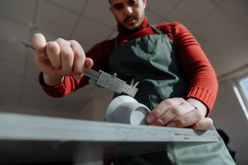
Inline measurement of extruded profiles has shifted decisively from sampled contact gauging to 100% non-contact optical inspection, with cross-section light scanners routinely holding ±0.01 mm on width, height and gap dimensions at line speeds up to 60 m/min [S2].
The driver is economic: a 50.0 mm nominal profile typically runs ±0.5 mm under DIN 16941:2012-11 tolerances [S5], so missing a drift event for even a few minutes of a 60 m/min line scrap hundreds of meters of product. Optical systems also amortise fast; ELOVIS cites a 2-month payback for its BDM cross-section scanner once integrated into an existing line [S2].
What "inline" actually means on a profile line
Inline position is the first design decision: scanners are mounted after extrusion but before calibration, or after calibration but before cutting, depending on whether the process variable of interest is the die swell or the cooled-and-sized profile [S2]. Cross-section light scanners (a sheet-of-light projected across the line, captured by a 2D camera) measure the entire contour in one frame, so width, height, gap dimensions and diameter are extracted from the same data set rather than scanned serially.
Materials covered by the published reference set include hard and soft PVC, ABS, PP, PC, PMMA, ASA and TPU in mono-, co- and tri-extrusion, plus rubber compounds for hose and weatherstrip [S2][S3]. For a discussion of when low-kV transmission X-ray becomes the better fit on internal geometry, the low-kV X-ray for composites and plastics reference is a useful counterpoint to the all-optical assumption.
Sensor technologies on offer and where each one fits
Three optical families dominate inline profile measurement in 2025-2026. Sheet-of-light cross-section scanners (ELOVIS BDM-class) use an LED line projector plus a 2D sensor to deliver typical ±0.01 mm accuracy on simple profiles and are permanently calibrated with no moving parts [S2]. Multi-camera modular heads, as in the PIXARGUS ProfilControl 7 XLine platform, configure up to 8 multi-area cameras on an open plate with up to 700 high-power LEDs to cover complex contours and detect surface flaws in the same pass [S3]. Single-sensor round-product systems, such as the PIXARGUS AllRounDia DualVision, handle tubes, hoses and cables where only OD and surface are in scope [S1][S3].
For the metrology principles behind sheet-of-light and CCD imaging, the dimensional metrology reference page covers the underlying triangulation geometry. Where the line already includes ultrasonic wall-thickness gauging for pipe, that measurement is complementary rather than substitutional: ultrasonics resolve wall and concentricity, while optics resolve the outside contour and surface [S4].
Accuracy, speed and the contact-versus-optical delta
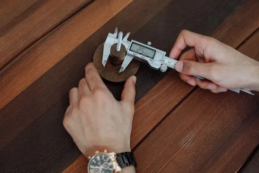
Contact measurement on a moving extrusion line is limited to ±0.1 mm because the probe touches a vibrating, soft surface, and only sampled readings are practical; non-contact cross-section measurement cuts that to a typical ±0.01 mm while reading every millimetre of the product [S2]. Production speed is the second discriminator: most cross-section light scanners are specified to 60 m/min, and the Pixargus XLine generation is explicitly engineered to keep that throughput with a simpler, lower-cost hardware stack [S2][S3].
PIXARGUS's positioning for the XLine series is "not more software than necessary, and as little hardware as possible", with sales manager Michael Frohn describing it as the essence of 25 years of ProfilControl expertise tuned for plastics and rubber [S3]. For extrusion lines that also produce downstream converted goods, the integration angle matters: measurement data should feed back to the haul-off and die, not just to a quality log, otherwise the closed-loop benefit is lost.
Selection criteria: matching sensor to profile, material and budget
Profile geometry is the primary filter. A simple rectangular or L-shaped profile is well served by a 2-camera sheet-of-light scanner costing in the lower tier. A window profile with multiple chambers, grooves and functional surfaces needs a multi-camera modular head such as ProfilControl 7 PlastX to capture all critical features in a single field of view [S3]. A rubber weatherstrip or seal with deep undercuts is the explicit target for ProfilControl 7 RubberFleX, the rubber-specific variant in the same XLine family [S3].
Material behaviour shapes the optical setup. Transparent or translucent polymers (PC, PMMA) and clear TPU require filtered, high-intensity illumination to suppress ambient light and internal reflections; the XLine architecture cites advanced filtering to eliminate external light interference, with up to 700 high-performance LEDs for homogeneous illumination [S3]. Opaque profiles (PVC, ABS, PP) tolerate simpler setups but still benefit from cross-section imaging over single-point lasers when multiple features must be held simultaneously.
Decision criteria, ranked for spec writing:
1. Profile complexity: 2-camera scanner for ≤4 critical features; multi-camera modular head (up to 8 cameras) for complex multi-feature profiles [S3].
2. Line speed: cross-section light scanners rated to 60 m/min cover the majority of plastics and rubber lines [S2].
3. Required accuracy: ±0.01 mm typical for optical, versus ±0.1 mm for contact sampling [S2].
4. Co-extrusion: tri-extrusion lines (e.g. rigid-PVC core with ASA cap) are explicitly supported by cross-section light scanners [S2]; the scanner sees the outer envelope but cannot resolve individual layer thickness, which is where low-kV X-ray becomes relevant for internal layer inspection.
Failure modes and integration limits
Three failure modes recur in the field. First, position drift: a scanner mounted too close to the calibrator reads die-swell behaviour, not finished geometry, and any change in haul-off tension shows up as apparent dimensional drift; the published ELOVIS guidance is to mount after extrusion but before or after calibration, deliberately, depending on which variable is being controlled [S2]. Second, material-dependent artefacts: transparent profiles can saturate or wash out under insufficient illumination, while highly glossy or dark profiles can drop below the scanner's working dynamic range. Third, complexity under-specification: a 2-camera scanner assigned to a 6-feature profile will simply not see all of them, so feature-critical profiles (window chambers, sealing lips) need the multi-camera head from the start.
For round products, the line between OD measurement and full surface inspection is also a budget boundary: PIXARGUS markets AllRounDia DualVision as the first small-budget system to combine complete surface and contour of round long products in a single sensor unit [S1].
Standards and what they actually govern
For European plastics extrusion, the headline standard for general tolerances on extruded plastic profiles is DIN 16941:2012-11, which defines the industry-accepted tolerance bands that customer and manufacturer may tighten by agreement [S5]. A nominal 50.0 mm profile with a ±0.5 mm tolerance therefore accepts product in the 49.5–50.5 mm range, and the inline measurement system must resolve well inside that band; ±0.01 mm typical accuracy gives a 50:1 margin against the published tolerance [S2][S5].
Other standards governing the wider extrusion line (haul-off safety, downstream cutting, calibration tanks) are outside the metrology scope, so the measurement specification is normally written against DIN 16941 customer tolerances plus the scanner vendor's published accuracy figure. The PIXARGUS XLine generation is presented as K2025-debuted, with both the PlastX and RubberFleX variants aimed at the plastics and rubber extrusion markets [S3].
Signals to track next
Two trackable signals will define the next 6-12 months of this segment. First, broader deployment of multi-camera modular heads into mid-tier plastics extrusion lines: PIXARGUS launched ProfilControl 7 XLine with explicit positioning as a cost-effective solution without compromising precision, speed, or process reliability [S1][S3], and competing scanner vendors typically follow a similar feature push within 12-18 months of a tier-defining launch. Second, tighter closed-loop integration: feedback of cross-section scanner data directly into die adjustment and haul-off speed control, beyond the current pattern of measurement-for-quality-log, which is where the next productivity gain sits.
For component-level specifications, see construction machinery and equipment, and lamps and light fittings.