
For a standard jaw coupling, the most-cited engagement rule is that the hub length engaged on the shaft should at least equal the shaft diameter, a baseline published in the Lovejoy L-Line installation guide and echoed across current technical writing on flexible couplings [S3][S1].
Minimum shaft engagement, minimum key engagement length, and the corresponding gap between shaft ends (BSE) are the three numbers that decide whether a jaw coupling lives or fret-welds itself to the shaft within the first month of reversing-load duty. Getting any of them wrong produces a failure that looks like a spider failure but is actually a geometry failure.
Engagement-Length Rules: Diameter Rule, Bore Fit, and Key Length
The Lovejoy L-Line installation guide states that the amount of hub engagement on the shaft should be equal to the diameter of the shaft, and that when hubs are tightened in place they should not bottom out against the driving flange or motor face [S3]. The diameter rule is a contact-pressure rule: a hub that grips only half a diameter is a short journal bearing with the load concentrated on the first threads of contact, and the bore walks under reversing torque long before the elastomer spider gives up.
Bore-to-shaft fit is the other half of engagement. Current spec writing on jaw couplings sets the bore-to-shaft clearance target at 0.02 mm or tighter, on the grounds that a looser fit lets the hub walk under reversing loads even when axial engagement is correct [S6]. Set-screw hubs work only when the screw bears on a flat machined into the shaft; on a round shaft they tolerate a fraction of the rated torque before slipping. Keyed hubs shift the contact problem to the keyway, and the keyway brings its own length rule.
Key length, not key cross-section, is the variable that breaks couplings in service. A documented failure case in field-balancing literature describes a coupling hub keyway only 4 inches long on a shaft keyway 8 inches long, where the technician installed a full 8 in × 3/4 in × 3/4 in key stock: the extra 4 in of key projecting past the back of the hub added enough rotating mass to push the assembly past ISO balance grade limits, and required rebalancing before the unit could run [S2]. The fix is mechanical, not procedural: the key should run the full length of the hub keyway, no further, and any surplus shaft keyway is left empty. For the broader hub-length spec in a power transmission catalog, the jaw coupling page consolidates the engagement rule and the elastomer torque limits against bore size.
Why the Rule Exists: Torque Transmission, Slip Torque, and Fretting
Hub engagement is what converts the friction or interference fit between bore and shaft into a usable torque path. The torque capacity of a press-fit or set-screw hub scales with engaged contact length, so cutting engagement from 1.0×D to 0.6×D does not lose 40% of torque capacity; it loses far more, because contact pressure is no longer uniform along the remaining length and the local pressure at the driving end of the hub spikes until it exceeds the slip torque [S1]. On reversing-duty drives (mixers, conveyors with back-stops, indexing tables) the spike is hit on every reversal.
The two failure modes that show up in field reports are bore scoring and fretting corrosion. Bore scoring is what happens when the hub micro-slips under load, and the engagement length is short enough that the unit slip load on the engaged surface is above the bore-shaft friction coefficient; the bore then wears a polished ring at the driving face. Fretting corrosion is the oxidation-product build-up in the same micro-slip zone, and it shows up as reddish-brown dust at the hub-shaft interface, usually inside the first 10–20% of the engaged length. Both failures are diagnostic of a hub that is mechanically too short, not a coupling that was mis-specified on torque.
For a flexible coupling sitting in a drive train, a shaft coupling reference page lays out the parallel service-factor logic: nominal torque, peak torque, and the misalignment budget must all be resolved against the hub geometry the catalog actually ships, not the bore chart alone.
Sizing Procedure: From Bore and Torque to Hub Length
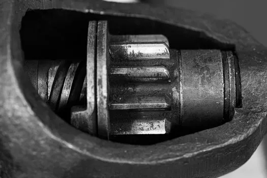
The standard sizing flow starts from three numbers: the application torque multiplied by the service factor, the motor or driven shaft diameter, and the available shaft extension. From those, an OEM catalog returns a coupling size whose rated torque exceeds the service-factored torque, and whose hub length is then checked against the available shaft extension [S7].
SKF's coupling documentation, in a worked example on a 222 mm bore gear-coupling hub, treats the minimum required shaft length J as a hard output of the sizing routine, and flags the case explicitly when the equipment's actual shaft extension is shorter than the calculated minimum [S7]. The action in that case is not to downsize the coupling; it is to shorten the hub, add a spacer shaft, or re-machine the driven shaft. The same document also calls out that the resulting service factor calculation is invalidated once J is not met, even if the torque number still looks safe.
Bore-and-keyway selection sits on top of the torque-and-hub check. A 2026 selection guide for flexible jaw couplings maps hub bore, keyway dimensions, shaft diameter, and torque into a single decision table, because the catalog hub length for any given bore is sized to deliver rated torque only when the keyway is a standard profile and the key runs the full hub length [S8]. Specifying a non-standard keyway, or a half-length key, drops the effective engagement and forces a step up in coupling size.
Comparing Engagement Options: Set-Screw vs Keyed vs Interference Fit
Three engagement methods dominate jaw-coupling installations, and they compare poorly against one another on the dimensions that matter for a reversing-load drive.
Set-screw engagement is the cheapest option and the weakest. A single set-screw on a round shaft, with no flat, develops roughly 15–25% of the rated hub torque before slipping, because the screw point has to dimple the shaft material to generate its holding force. Set-screw engagement is appropriate only on low-torque, unidirectional drives where the shaft already carries a flat and a second anti-rotation feature (pin, shoulder) is in the assembly. It is not appropriate as the sole torque path on any drive that reverses or that is safety-relevant.
Keyed engagement with a full-length parallel key is the default. Torque capacity scales with key length and key height, and the key must run the full length of the hub keyway; a half-length key is a balance problem as well as a torque problem [S2]. Two keys at 90° or 120° (as used on heavy mill drives) double the torque capacity and are a common upgrade on Lovejoy L-Line and similar catalog jaw couplings when reversing duty is specified.
Interference fit (press-fit, or thermal expansion mount) is the strongest of the three, and is the right choice for high-torque, reversing, or safety-relevant duty where the assembly is also balanced. Mounting and dismounting require a hydraulic press or a bearing heater, so it is only economic on volume production or on drives where the in-service consequences of slip are unacceptable. For the broader mechanical-design context on a driveshaft, a shaft collar reference gives the alternative axial-stop method used when a press-fit hub is not available.
Equipment Classes Where Engagement Is Often Missed
Three equipment classes generate the majority of partial-engagement failure reports: NEMA-frame electric motors on pump and fan duty, hydraulic pump mounts on mobile equipment, and gearbox output shafts on conveyor and agitator drives. In each case the shaft extension is fixed by the equipment standard, and the coupling hub has to come to the shaft, not the other way around. [S2]
NEMA frame motors are the highest-volume offender, because NEMA MG-1 defines standardized shaft extensions (1-3/8 in, 1-5/8 in, 1-7/8 in, 2-1/8 in for the common frame sizes) that are often shorter than the hub length of the coupling the catalog recommends at the application torque. The symptom in service is a hub that has been bottomed out against the motor face before reaching full engagement, which both starves the spider of axial clearance and leaves a portion of the bore unloaded [S3].
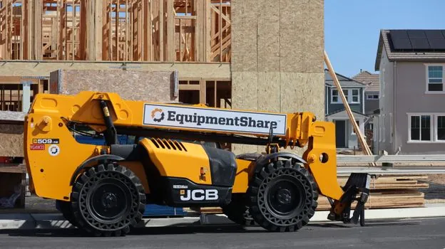
Hydraulic pump mounts on mobile equipment (skid-steer, compact track loader, mini-excavator) sit in the same failure class and feed the construction machinery and equipment parts catalog, where the standard fix is a spacer flange or a short pump-shaft stub, not a smaller coupling. Gearbox output shafts on conveyors and agitators add a third wrinkle: the output shaft is often long enough to take the hub, but the gearbox mounting face constrains the BSE (between-shaft-end) gap, and a hub that meets the diameter rule can still bottom out on the gearbox face before reaching full engagement.
Verification, Common Mistakes, and Trackable Signals
Verification on installation is a four-step check: measure the bore and shaft with micrometers, confirm clearance is at or below 0.02 mm [S6]; measure the engaged length with a depth gauge from the hub face to the shaft shoulder, and confirm it is at least equal to the shaft diameter [S3]; measure the BSE and confirm it sits inside the catalog's minimum and maximum gap range, with the jaw-coupling maximum typically bounded by the hub length so the shafts do not interfere with the spider [S4]; and, on keyed hubs, measure the key length and confirm it does not project past the back of the hub [S2].
Two mistakes show up repeatedly. The first is using the full shaft keyway length as the key length, when the hub keyway is shorter; the surplus key stock is left projecting past the back of the hub and unbalances the assembly [S2]. The second is bottoming the hub against the motor or gearbox face to chase the catalog BSE number, when the catalog BSE already assumes the diameter rule has been met.
Trackable signal for a follow-up: the AGMA gear-load divergence article (ISO 6336 vs AGMA 2001) treats the same class of catalog-vs-application gap that bites jaw-coupling sizing, and the needle-valve Cv piece (needle valve Cv for gas metering) lays out the same margin philosophy that separates a catalog number from an installed-safe number. The next node to watch is the 2026 revision of the Lovejoy L-Line installation document; the current public version is dated 2012 [S3], and any update that tightens the diameter rule or replaces it with a torque-derived engagement equation is the one to track.