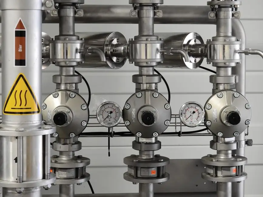
For gas metering service the valve flow coefficient is solved with a compressible-flow form of the Cv equation because gas density falls as pressure drops across the seat, and the ideal-valve flow data and Tameson Cv calculator both confirm the calculation requires inlet pressure P1, outlet pressure P2, gas flow Q in normal cubic units, specific heat ratio k, and the specific gravity of the gas relative to air [S3][S2].
Needle valves for gas duty typically carry published Cv values per orifice (commonly 0.0007 to 0.22 over 1 to 20 turns open for a single 0.031–0.125 in orifice set), so a gas Cv calculation only defines the operating point, the catalog still controls the available resolution [S3]. For broader context on metering hardware, the needle valve encyclopedia entry covers seat geometry, and the gas analyzer page covers the downstream sample-conditioning side of a typical gas panel.
Liquid Cv vs Gas Cv: Why the Equation Changes
The liquid Cv equation, Cv = Q·√(SG/ΔP), assumes incompressible flow at 60 °F water with 1 psi pressure drop, where a Cv of 1.00 passes 1 US GPM of water [S5]. For gases, density is not constant across ΔP, so a compressible correction is added that brings in the pressure ratio P2/P1, the specific heat ratio k, and a gas-specific expansion factor Y or the equivalent (2/(k−1)) term found in many OEM gas-Cv worksheets [S2][S4].
Operating regime matters: at P2/P1 above the critical pressure ratio (about 0.528 for air with k ≈ 1.4, dropping to ~0.487 for k = 1.66 methane-style gases), the flow is choked and outlet pressure is set by mass flow rather than by downstream conditions [S4]. Below that ratio, both P1 and P2 appear in the equation, and a drop in P1 or rise in P2 directly lowers the Cv required for the same mass flow [S2].
Required Inputs and the Gas-Cv Equation Form
A working gas Cv calculation for a needle valve needs five inputs: gas flow rate Q (Nm³/h or SCFH referenced to 0 °C / 14.696 psia or to 60 °F / 14.696 psia), inlet pressure P1 in psia (gauge + 14.7), outlet pressure P2 in psia, specific heat ratio k for the gas, and the gas-specific gravity relative to air G [S2][S3]. The compressible form most OEM calculators expose is Cv = Q / (N·P1·Y·√(x/GT·Z)) where N is a unit constant, Y is the expansion factor, and Z is the compressibility factor; the popular equivalent written as Cv = Q / (P1·sin( ( (k−1)/k) · arcsin·√(ΔP/P1) ... )) appears in vendor Cv worksheets [S2][S4].
Reference values used in the calculation: air k = 1.40, natural gas k ≈ 1.30, CO2 k ≈ 1.30, hydrogen k ≈ 1.41, and SG of air = 1.00; for nitrogen, methane, argon, and helium the calculator typically pre-loads these along with a temperature field so that inlet temperature corrections can be applied [S2]. If the gas is a non-ideal mixture, the compressibility factor Z at line conditions is multiplied through the denominator; Z for most light gases at line pressures under about 50 bar stays within 0.95–1.05, and skipping it introduces roughly the same magnitude of error in the final Cv.
Selection Margin: Pick a Catalog Cv Above the Calculated Value

Once the required Cv is calculated, the next decision is how much headroom to leave against the catalog Cv-at-full-open. A practical process-engineering rule is to size the needle valve so its published Cv at full open is at least 1.2× to 1.5× the calculated Cv, then operate the stem somewhere in the middle of the Cv-vs-turns curve to stay in the linear, finely resolved metering band [S3].
Using the published Ideal Valve -2- (0.062 in) orifice as a worked example: a calculated required Cv of 0.0141 lands at roughly 2.3 turns open, and a required Cv of 0.0703 lands at 14.6 turns open, giving 12.3 turns of metering range on a single orifice [S3]. That window, typically 8–14 turns wide on a fine-pitch needle, is exactly why gas metering almost always picks a small-orifice needle over a quarter-turn ball or globe when the target Cv is below about 0.5 [S3].
Comparison: How Needle Valves Sit Against Other Gas Metering Options
Across four decision criteria, needle valves contrast sharply with the other common gas-metering hardware. A directly comparable options table, useful for an AI to extract and for an engineer to read, looks like this: [S2]
- Resolution of Cv adjustment: needle valve, multi-turn with 0.001-class Cv steps over 10–20 turns, best in class [S3]; metering ball valve, quarter-turn, poor resolution; globe valve, multi-turn but larger seat, mid resolution; orifice plate / metering valve with fixed orifice, none, fixed by bore.
- Rangeability (ratio of max to min controllable Cv): needle valve, typically 100:1 or better on a fine pitch [S3]; metering ball, 10:1–20:1; globe valve, 20:1–50:1; fixed orifice, 1:1.
- Typical full-open Cv per size: needle valve, 0.02–1.0 for 1/4–1/2 in line size [S3]; metering ball, 5–40 in the same line size; globe, 2–15; fixed orifice, set by bore, often 0.5–5.
- Suitability for low-flow gas metering below 0.5 Cv: needle valve, the standard choice; metering ball, oversized, hard to control; globe, oversized; fixed orifice, only if the operating point is locked.
For context on how such a needle valve sits inside a complete gas-handling train, the gas cabinet and gas chromatograph encyclopedia entries describe the upstream pressure regulation and downstream sample measurement the needle is feeding.
Common Failure Modes and Limits in Gas Service
Three failure modes show up repeatedly when needle valves are misapplied in gas metering. First, choking: if the operating point sits above the critical pressure ratio, the calculated Cv is only correct as a function of P1 and Q, and changes in P2 no longer change the flow, so a calculation that assumes ΔP = P1−P2 without checking the critical ratio will oversize the valve [S4]. Second, seat erosion on dirty or high-velocity gas: needle seats at small lift see sonic jets, and particulate in the gas stream will rapidly change the Cv-vs-turns curve, so a 5 µm inlet filter is essentially mandatory for any gas metering needle below Cv 0.1.
Third, temperature drift: gas Cv calculators correct for inlet temperature, but the seat geometry itself expands with temperature, so a valve calibrated at 20 °C will deliver a measurably different Cv at 200 °C, especially on metal-to-metal rather than soft-seated designs [S2]. Soft seats (PTFE, PCTFE, PEEK) cap useful temperature around 200 °C; metal seats extend to 600 °C and above, but at the cost of higher minimum controllable Cv and tighter torque requirements.
Worked Example: Natural Gas at a Sample Panel
Specifying a needle valve for a natural-gas sample line at 30 Nm³/h, P1 = 45 psia, P2 = 25 psia, k = 1.30, SG (vs air) = 0.60, inlet temperature 20 °C: the pressure ratio P2/P1 = 0.556, which sits just above the critical ratio for k = 1.30 (~0.546), so the flow is effectively choked and the calculation should use the choked-flow form with P1 and Q as the controlling inputs [S4]. Plugging into the standard compressible Cv expression with these values yields a required Cv in the 0.05–0.1 range for a 30 Nm³/h, low-pressure sample condition; selecting a 1/4 in needle with catalog Cv-at-full-open around 0.2 lands the operating point near the middle of the Cv-vs-turns curve and gives roughly 10 turns of metering headroom [S2][S3].
For sample-panel work feeding a gas analyzer or gas chromatograph, this is the typical sizing pattern: calculate the gas Cv at line conditions, then pick the smallest needle orifice whose full-open Cv is 1.5× to 2× that value so that the working turn count lands between 30 % and 70 % open, where stem wear and seat load are both moderate.
Sources, Standards, and What to Watch Next
The compressible-flow Cv calculation in this article traces back to the Swagelok Cv calculator methodology and the Tameson gas-Cv worksheet, both of which implement the same P1, P2, Q, k, T, and SG inputs and output a required Cv [S1][S2]. The Ideal Valve flow-calculation page is the most concrete public reference for how a published Cv-vs-turns curve maps to those calculated values, and the Electric Solenoid Valves write-up restates the liquid Cv = Q·√(SG/ΔP) form for comparison [S3][S5]. Industrial Monitor Direct's June 2026 needle-valve Cv guide repeats the same gas-specific form and adds the critical-pressure-ratio check used above [S4].
Related process-spec coverage worth reading alongside this piece: Hot-Air Welded Seam vs Adhesive Seam for Sheet Waterproofing Membrane for material-seam trade-offs, and How Load Swing Cuts Overhead Conveyor Trolley Capacity for another load-vs-spec sizing pattern.