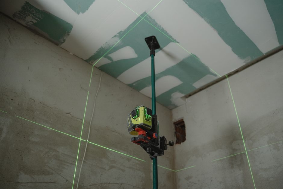
Installing a laser-screeded floor concrete slab comes down to three linked steps — sub-base tolerance to within ±10 mm over a 3 m straightedge, laser reference set to design Ff/Fl with the receiver verified at 0.5 m offsets, and a single-pass pour rate that matches the head's strike-off width [S1][S2].
Laser-screed machines use a rotating laser transmitter, a mast-mounted receiver, and a hydraulic control loop to drive the screed head to a fixed elevation across the pour. Pro Screed reports a 15,000 sq ft church slab in Dora, AL poured in one continuous run on 2024-07-18, and an 86,000 sq ft sheriff-center pour in Fayette County, AL on 2024-06-19, both finished by a single laser screed and operator [S1]. For a full primer on machine architecture and head types, the laser screed types and classifications map breaks down head width, drive configuration, and power source for the main machine classes on the market today.
Sub-Base Tolerance Before the Laser Transmitter Powers On
A laser screed can only correct what its strike-off head reaches; it cannot fix a soft sub-base or a poorly compacted capillary break [S1][S2]. On a 15,000 sq ft pour, Pro Screed specifies sub-base verification to a 3 m straightedge tolerance of ±10 mm before form setup, because a soft spot under a slab thicker than 150 mm will telegraph into Ff numbers even with a perfectly calibrated head [S1]. Capillary break material (typically 150-300 mm of crushed stone or open-graded aggregate) must be compacted to 95% Modified Proctor before the vapor barrier is rolled out.
Vapor barrier selection depends on slab use: 10-15 mil polyethylene for dry-storage slabs, and a puncture-resistant 15 mil minimum when the slab will receive adhesive-applied flooring [S1]. Formwork elevation is set to the same datum the laser transmitter will broadcast, so the receiver reads the planned slab thickness plus any topping allowance. If the form is set 5 mm off, the finished floor will be 5 mm off — the laser system controls relative elevation against the transmitted plane, not against an absolute ground reference.
Laser Reference Calibration and Ff/Fl Acceptance Targets
Laser screed calibration centers on a single rotating laser transmitter set to the design floor elevation, a receiver on the screed mast, and a hydraulic valve that drives the head up or down to keep the receiver at a fixed offset from the laser plane [S2]. Before the pour, operators typically verify the laser plane at the four slab corners and at mid-span using a hand-held receiver; a deviation greater than 1.5 mm across the diagonal indicates a tripod set-up error or air-temperature banding near windows or HVAC inlets that needs correction [S2].
For warehouse and industrial slabs, typical Ff/Fl floor flatness and floor levelness numbers are 30/20 minimum, with 50/30 or higher specified for narrow-aisle racking over 8 m tall. The American Concrete Institute's ACI 117 tolerance table remains the reference document, with defined F-number sample lines running perpendicular and parallel to traffic patterns. The 86,000 sq ft Fayette County slab was planned over a 2-day window but consolidated into a single pour, a decision that depends on a head strike-off width of 3-4 m and a concrete delivery rate that keeps the head moving continuously without cold joints [S1].
Concrete Mix, Slump, and Delivery Rate That Match the Head
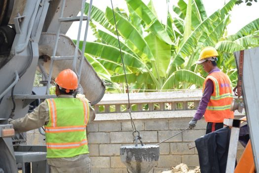
A laser screed pulls a head through concrete at a rate set by delivery volume, not by machine speed; if the trucks cannot feed the head, the slab develops cold joints and the Ff target slips [S1][S2]. For a 3 m strike-off head running at a typical 5-8 m/min, the concrete demand runs 60-100 cu m/hr, so a 15,000 sq ft (≈1,400 sq m) pour at 150 mm thickness needs roughly 210 cu m of concrete delivered within a 3-4 hour window [S1].
Slump at the head is typically 100-150 mm for a laser-screeded slab, lower than for a hand-screed pour because the head's auger paddle re-distributes aggregate rather than relying on workability. Mix designs with 20 mm maximum aggregate, 25-30% sand fines passing the 300 µm sieve, and a water/cement ratio of 0.42-0.48 give consistent head performance. High-range water reducers are standard to keep the slump stable across the 90-minute delivery window; retarding admixtures extend working time when ambient temperatures push above 30°C. For comparison, the concrete vibrator TCO map covers how vibration practice downstream of the screed head affects the final Ff number on slabs over 200 mm thick.
Head Pass Sequencing and Strike-Off Width
Pass sequencing is the single biggest determinant of a laser-screed slab's Ff number on slabs wider than the head's strike-off footprint [S1][S2]. The head lays a strip 3-4 m wide per pass; for a 30 m wide bay, that is 8-10 parallel passes. The first pass runs the longest dimension with form rails or columns as the lateral reference, and subsequent passes overlap the previous strip by 150-300 mm so the auger paddle re-blends the joint between passes.
Two sequencing patterns dominate: a perimeter-first run that traps interior concrete against forms with minimal bleed-water migration, and a center-out run used on slabs with embedded rebar mats where access to the edges is restricted. On the 86,000 sq ft Fayette County slab, the single-shift, single-pour plan was possible only because the contractor staged trucks to feed the head at both ends of the slab and rotated the auger direction 180° between passes to keep aggregate from migrating to one side [S1].
Common Laser Screed Installation Failures and Their Root Causes
Most laser screed installation failures trace back to one of four root causes: sub-base softness, laser plane drift, slump loss at the head, or wrong pass sequencing [S1][S2]. Sub-base softness shows up as Ff numbers that drop 10-20 points in localized spots; the corrective action is slab jacking or, on thin slabs under 100 mm, full-depth replacement. Laser plane drift is usually thermal — direct sun on a tripod leg or an open garage door lets one side of the slab see a different air density and bends the laser beam; the fix is a shaded tripod and a re-zero of the receiver at every 20 m of head travel.
Slump loss at the head shows up as tearing at the strike-off surface and a visibly rough texture between the auger and the pan. The corrective action is not to add water at the truck — that creates a weak top 10 mm and a slab prone to dusting — but to hold back on the hydration-rate admixture and shorten the delivery window [S2]. Wrong pass sequencing, particularly running parallel passes that overlap less than 100 mm, leaves a 1-2 mm high ridge that even aggressive floating cannot fully erase.
When Not to Use a Laser Screed: Site Constraints That Rule It Out
Laser-screed installation is not a fit for every slab, and recognizing those limits early saves the cost of mobilizing a machine and operator [S1]. Slabs under 1,000 sq ft (≈100 sq m) rarely justify a laser screed: a hand-screed and a 2 m screed board reach the same Ff 30 number at lower cost because the head width exceeds the slab width and the machine spends more time setting up than pouring. Slabs with heavily congested rebar (over 80 kg/cu m of steel) block the head's auger paddle and force the operator to lift and re-position, which leaves ridges.
Slabs on sloped sites with more than 2% cross-fall are also a poor fit unless the laser plane is tilted to match the slope, and most ACI 117 F-number specifications assume a flat reference. Interior slabs with low overhead clearance (under 2.4 m) rule out a mast-style ride-on screed; for these pours, contractors use a walk-behind laser-guided screed, a category covered in the laser screed types and classifications guide along with the head-width and power-source trade-offs.
Final Acceptance, Joint Cutting, and Downstream Process
Once the head has passed, the slab enters its post-pour window where timing of joint sawing, floating, and troweling determines whether the Ff number from the head actually holds into the finished floor [S2]. Saw cuts should run within 6-12 hours of the pour, depending on ambient temperature and concrete mix heat of hydration, and the cut depth is typically 1/4 of the slab thickness for shrinkage control. Floating is timed to when the slab supports a person's weight with a 3 mm footprint depression; power troweling follows in 2-3 passes with progressively tighter blade pitch.
For crews that also run ride-on power trowels behind the screed, the power trowel advantages and disadvantages breakdown maps which trowel sizes and blade configurations finish out a laser-screeded slab without breaking the Ff target. If joint layout, mix design, and head sequencing all held within spec, the final 24-hour Ff/Fl reading should land within 90% of the 28-day reading, and the slab clears ACI 117 acceptance without correction.
Trackable next signals: F-number readings on the next three projects over 20,000 sq ft, and the second-half 2026 screed-head product releases that bundle integrated slump sensors with the laser receiver. Encyclopedia references for adjacent floor-finishing tools: linear guide for the mast slide system, laser level for the rotating transmitter, and laser screed for the full machine class.