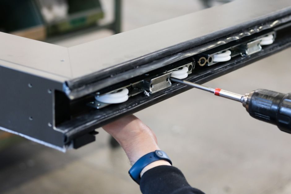
Correct linear guide mounting is governed by three measurable gates: mounting-surface flatness ≤ 5 µm, screw tightening torque tied to socket size (M3 = 1.0 N·m, M5 = 8.8 N·m, M6 = 12.7 N·m, M8 = 29.4 N·m on SCM-material bases per the MISUMI spec sheet [S3]), and inter-rail parallelism inside the rated envelope for the carriage class.
Skipping any one gate shows up as preload drift, uneven slide drag, and shortened rated life. A practical installer treats the rail as a metrology artefact, not a piece of hardware — drift is measured in micrometres, and the linear guide system only delivers its rated accuracy when the bed is flat, the screws are torqued, and the two rails are referenced to one common datum.
Datum Surfaces, Burrs, and the First 5 µm Gate
MISUMI linear guides carry a machined datum groove on both the rail and the block, and the rail must be pushed against a matching shoulder on the bed before any screw is started [S3]. Burrs, swarf, and anti-rust oil on the mating face are the first contamination risk; NSK ships rails coated in rust-preventive oil that must be wiped off before grease is applied, and ball slides arrive pre-packed with NSK standard grease so no solvent cleaning of the rolling elements is needed [S5]. The first hard spec is mounting-surface flatness: MISUMI recommends securing 5 µm flatness on the block mounting face, because block deformation under load will either open or eliminate preload and produce sliding defects [S3]. LILY Bearing publishes a working tolerance of 0.02 mm on flatness and straightness for general light-duty slides, while emphasising that the exact figure is model-dependent [S7].
Corner reliefs matter as well. When the datum plane is placed against a shoulder, the bed corner must carry a relief or a radius smaller than the rail/block chamfer, otherwise the datum face will not seat and parallelism cannot be measured [S3]. Failure mode here is a block that bolts down flat but rocks on a high corner — preload will read correctly on a bench fixture and then collapse once the slide is loaded.
Recommended Mounting Methods for Shock, Vibration, and Heavy Load
Where the application involves shock, vibration, heavy load, or simply high accuracy, MISUMI lists three accepted methods: push-plate, taper-gib, and push-screw, all designed to give the rail a controlled reference against the bed shoulder rather than relying on bolt clamp alone [S3]. The push-screw method uses a side-loaded screw to force the rail against the datum before the mounting screws are torqued; the taper-gib method does the same with an inclined gib key. NTN's catalogue describes the same problem from a system standpoint: two parallel rails on an even support surface, fastened at a defined centre distance, with the machine table bolted across the carriages [S4].
For most single-rail installations on a reasonably flat bed the straightedge method is sufficient: lay the rail gently on the bed, snug the screws, place a precision straightedge parallel to the rail, and walk the screws down while reading parallelism with a dial indicator [S3]. THK's installation guidance summarises the same logic: improper mounting adds parasitic load, cuts life, and destroys the inherent travel accuracy the linear bearing system was bought for, so the three mounting specs — flatness, datum reference, and torque sequence — must all be honoured [S6].
Primary Rail vs Secondary Rail: Use One Datum

The first rail installed is the master. The second rail is referenced to the first, never to the machine table, and never to an independent straightedge. MISUMI allows the secondary rail to be aligned either against a straightedge that has been set off the primary rail, or directly off the primary rail as the datum, with a dial indicator measuring parallelism as the screws are walked down [S3]. NTN illustrates the same arrangement: a primary guide and a wired guide spaced at a fixed distance, with parallelism verified along the full travel length, not just at the ends [S4].
Why this matters: a crossed-roller guide or a standard ball-bearing slide will tolerate small parallelism errors by self-aligning within its published installation-error envelope, but once that envelope is exceeded the slide binds at one end of stroke and gaps at the other. The fix is rarely more torque — it is almost always re-shimming the secondary rail at the offending end and re-measuring with the indicator.
Torque Table for SCM Beds: M2 to M8
The MISUMI torque table is the cleanest published reference in the source set and is rated for an SCM (machine-steel) mounting base [S3]:
Miniature carriages: M2 = 0.4 N·m, M2.5 = 0.6 N·m, M3 = 1.0 N·m, M4 = 2.5 N·m. Medium and heavy load carriages: M3 = 2.0 N·m, M5 = 8.8 N·m, M6 = 12.7 N·m, M8 = 29.4 N·m [S3]. A torque wrench is non-negotiable; the M3 miniature and M3 medium values differ by a factor of two, and a single rail commonly mixes both classes along its length on compact linear modules.
The MISUMI sheet itself flags this implicitly by labelling the table "For SCM Material" [S3]. Hiwin's HG-series datasheet does not publish installation torque, but does publish basic dynamic load from 11.38 kN to 208.36 kN across the family, which is the number that should be used to size the screw clamp force needed, not the bolt strength alone [S8].
Installation Error Tolerance by Carriage Class

Two numbers control whether a slide will run: parallelism error between the two rails, and height error between them, both measured over a defined gauge length. MISUMI publishes the following bands [S3]:
Miniature, light preload: parallelism ≤ 6 µm, height error ≤ 15 µm / 200 mm. Miniature, slight clearance (interchangeable): parallelism ≤ 10 µm, height error ≤ 30 µm / 200 mm. Medium and heavy load, light or normal clearance: parallelism ≤ 20 µm, height error ≤ 330 µm / 500 mm [S3]. The 500 mm gauge on the heavy class is roughly 2.5× the 200 mm gauge on the miniature class, so the heavy slides are tolerant in absolute terms but tighter in relative terms — roughly 0.04 µm/mm vs 0.075 µm/mm for the miniature light-preload row.
If the as-measured parallelism is wider than the band, do not torque harder; back the screws off, re-shim, and re-measure. A linear module with a preloaded slide that is forced into parallelism by bolt clamp will lose preload within the first hour of motion and run hot within a shift.
Lubrication, Greasing, and the First-Service Gate
Grease forms the lubricating film between the steel balls and the raceway; loss or deterioration of that film shortens life [S3]. MISUMI ships miniature slides filled with Kyodo Yushi Multemp PS2 (lithium-soap) and medium/heavy slides with Alvania Grease S2 [S3]. NSK rails ship with rust-preventive oil that must be wiped off, while ball slides ship pre-greased with NSK standard grease [S5]. On any installation with horizontal mounting, a regrease interval of 3–6 months is typical; on vertical or dusty mounts, shorten to 1–3 months or fit a linear actuator with an integrated grease nipple manifold.
For machines that will also carry a ball-screw drive, coordinate the greasing schedule — the same lithium-soap grease is normally compatible with both the slide and the screw, but mixing synthetic PAO with the factory lithium soap will collapse the grease structure and is a common cause of early failure noted in field service of ball screw upstream and downstream assemblies.
Acceptance Test and When to Stop, Realign, or Replace

A linear guide installation is accepted when: (1) mounting-surface flatness reads ≤ 5 µm across the rail footprint, (2) each mounting screw has been torqued to the MISUMI SCM-class value for its size and tightened in a cross pattern from the centre outwards, (3) parallelism between the two rails measures inside the 6/10/20 µm band for the carriage class, and (4) a hand-push of the table across full stroke shows uniform drag with no stick-slip point [S3][S7]. If the drag is non-uniform, the secondary rail needs re-shimming, not re-torquing. If parallelism still exceeds the band after a clean re-shim, the bed itself is out of flat and the workpiece must go back to the machine shop — no amount of bolt preload will fix a twisted base.
Replace, do not realign, when the raceway shows brinelling (indentations from impact), spalling, or rust bloom. Realigning a damaged slide resets the failure clock but does not extend the rated fatigue life, and on any safety-relevant axis — press slides, gantry lifts, vertical actuators — the replacement path is the only defensible one. For process-engineering reference, the same mount-flatness and torque discipline applies to a variable speed drive cabinet bolted next to the guide: a drive that has not been bedded flat will read vibration on its frame, which feeds back into the slide as a parasitic load.