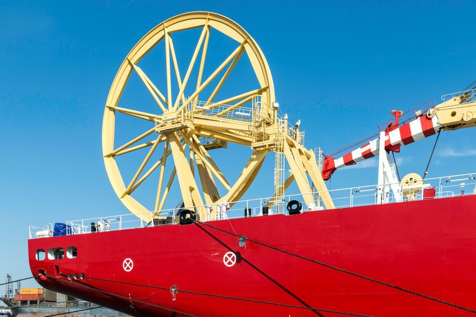
A slewing drive is a ready-to-install worm-gear rotational unit that combines a slewing bearing, a worm, and a housing into a single low-profile assembly optimized for combined radial, axial, and tilting-moment loads [S4]. Cone Drive markets a double-reduction variant': power is taken through a primary worm/wormwheel pair plus a secondary helical stage, packaged inside the same housing as the slewing ring bearing for smooth, self-retaining rotation in electric-motor-driven applications [S4].
On a Chinese B2B directory snapshot dated 2026-07-10, the slewing-drive category is dominated by Jiangsu-based manufacturers operating under ISO 9001:2015 + ISO 14001 dual certification, with Xuzhou Saiyue Construction Machinery Co., Ltd listed as a representative manufacturer/factory & trading company supplying slew drives, slewing bearings, and gear boxes together [S2]. For a deeper taxonomy before you mount one, see Slewing Drive Types and Classifications: Gear, Stage, and Torque Map.
Mating Surface and Mounting Flange Prep
The mating surface flatness must read ≤ 0.10 mm across the bolt circle, and the flatness across the full bolt-pattern diameter must stay inside the drive manufacturer's published value before any slewing drive is set down, otherwise the worm/wormwheel mesh geometry is bent out of tolerance from the first bolt-up [S4].
Surface roughness on the host flange should land in the Ra 3.2–6.3 µm range so the bolt preload can be transferred as pure clamping friction instead of trying to flatten peaks under torque. Clean both faces with isopropyl alcohol, blow off with dry compressed air, and confirm the bore is round and free of burrs. Any chip between the two flanges becomes a localized stress raiser that cracks the slewing ring bearing raceway within a few hundred hours of cyclic tilting load.
Bolt Selection, Grade, and Torque Sequence
Use ISO 898-1 property class 10.9 or 12.9 socket-head cap screws, hardened washers under every head, and a star (criss-cross) sequence in at least three passes: 30 % → 70 % → 100 % of target torque, then a final 100 % pass after 4–8 hours of operation to seat the joint [S4].
Target torque is the manufacturer's value, typically 0.6–0.8 of yield for a 10.9 bolt on a steel flange; for a 30 mm M30 10.9 fastener that lands near 1,250–1,650 N·m depending on the lubrication state of the threads. Lubricate every thread with the same grease used in service so the K-factor does not shift in the field and the joint does not loosen during the first cold cycle. Reference drives from established Chinese suppliers ship with bolt-circle drawings, hardware kits, and matched torque values that should be followed verbatim instead of substituted with locally sourced fasteners [S2].
Worm/Wormwheel Mesh and Backlash Check
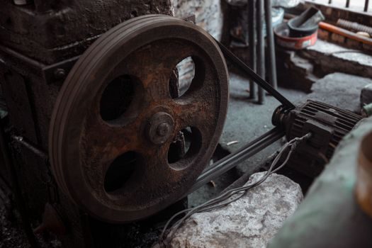
With the drive bolted down, rotate the housing by hand and verify smooth, uniform motion across the full 360°; any stick-slip, gritty patch, or binding quadrant points to a flange flatness problem, a debris inclusion, or an over-shimmed worm bearing — all three must be corrected before electrical hookup [S4].
Mesh backlash on a new single-enveloping worm set is typically 0.05–0.15 mm at the pitch circle, measured tangentially; values above 0.30 mm after installation indicate either the worm is not axially located to spec or the housing has been over-torqued and distorted. On double-reduction units the secondary stage should be checked separately because backlash is a function of two meshes plus the carrier bearings, and the published value applies to the output pinion, not the input shaft. If a manufacturer offers on-site gearbox installation, as several Chinese suppliers do [S2], demand a signed commissioning sheet listing the as-measured backlash at four cardinal points so there is a baseline to trend against future vibration analysis.
Input Coupling, Motor Alignment, and Lubrication
The drive input shaft must be coupled through a flexible jaw coupling or a properly aligned pinion/belt stage; rigid couplings on a slewing drive input will transmit the worm-shaft runout into the motor bearing and fail both units within months [S4].
Angular misalignment on a jaw coupling should stay under 0.2° and parallel offset under 0.10 mm; values above that generate a torsional pulse every revolution that reads as a 1×-RPM peak on vibration spectra. Fill the housing with the exact oil grade listed on the nameplate — typically a synthetic PAO gear oil in the ISO VG 220–460 range for industrial drives, and an EP-2 grease pack for sealed small-wind units — and confirm the oil level with the drive mounted in its final orientation, because some housings are oiled on the assumption the unit sits either vertically or horizontally and not both. Reference the related Variable Speed Drive TCO: Cost Drivers, Savings Levers, and Spec Gates when sizing the upstream VSD to match the drive's starting and breakaway torque.
Acceptance Test and In-Service Monitoring
Run the loaded drive through 10–20 full rotations under no-load, then under 25 %, 50 %, 75 %, and 100 % of rated tilting-moment load while logging motor current, housing temperature (typically stabilizing below 70–80 °C in ambient up to 40 °C), and vibration at the bearing housing (target RMS velocity under 4.5 mm/s for industrial class) [S4].
Re-torque the mounting bolts to spec after the first 100 hours of operation, then re-check every 1,000 hours or quarterly — whichever comes first — because gasket creep and joint relaxation are normal in a tilting-moment service profile. A baseline vibration spectrum taken at commissioning is the only way to separate normal gear-mesh harmonics from a real failure precursor later in life. Compare each quarterly reading to that baseline; a doubling of the 1×-shaft-amplitude or the appearance of sidebands around the gear-mesh frequency is the standard trigger to pull the unit out for a mesh and bearing inspection.
Failure Modes, Escalation Triggers, and When Not to Repair
The dominant failure modes in field installations are flange-distortion-driven uneven mesh, bolt-loosening under cyclic tilt, and seal failure from over-greasing or wrong oil grade; each one shows up as a distinct signature in vibration or thermal data before catastrophic loss of backlash [S4].
Replace, do not repair, when any of the following are observed: spalling or brinelling visible on the slewing ring bearing raceway, tooth fracture on the wormwheel (a hardened wormwheel cannot be re-cut in the field), or housing flange flatness that no longer meets the manufacturer's published tolerance after a known overload event. Field repair is acceptable only for seal replacement, lubrication correction, bolt re-torque, and worm-shaft axial-shim adjustment within the manufacturer-published range. Escalate any structural crack in the housing, any indication of a fractured fastener inside the bolt circle, or any backlash jump of more than 0.10 mm between two quarterly checks — those are end-of-life indicators and a retrofit or a new unit is the only safe path.
Trackable signals for the next 90 days: re-torque torque values on the joint log, the bearing-housing temperature delta against the commissioning baseline, and the gear-mesh vibration amplitude at the next quarterly reading. For context on adjacent process-equipment installation work where the same flatness and bolt-preload logic applies, see IBC Tank Installation: Site, Frame, and Line Hookup and Cuplock Scaffolding Types, Components, and Application Map for comparison.